© 2019 Thorlabs
5 Appendix
19
5.1.2 PDB450x Individual Technical Data
Operating Wavelength Range
RF OUTPUT Bandwidth (-3 dB)
DC - 150 / 45 / 4 / 0.3 / 0.1 MHz
RF OUTPUT Transimpedance Gain
1
)
10
3
/ 10
4
/ 10
5
/ 10
6
/ 10
7
V/A
RF OUTPUT Conversion Gain
2
)
0.53 × 10
3
V/W
0.53 × 10
4
V/W
0.53 × 10
5
V/W
0.53 × 10
6
V/W
0.53 × 10
7
V/W
1 × 10
3
V/W
1 × 10
4
V/W
1 × 10
5
V/W
1 × 10
6
V/W
1 × 10
7
V/W
Minimum NEP
DC to 0.1 MHz (Gain 10
7
V/A)
DC to 0.3 MHz (Gain 10
6
V/A)
DC to 4 MHz (Gain 10
5
V/A)
DC to 45 MHz (Gain 10
4
V/A)
DC to 150 MHz (Gain 10
3
V/A)
Note Make sure hat the transimpedance gain is set in such way, that RF OUTPUT is below saturation threshold!
1
) Values are given for high impedance load. For a 50 W load, values are to be divided by 2.
2
) Values are given at peak responsivity of the detector, for high impedance load. For a 50 W load, values are to be
divided by 2.
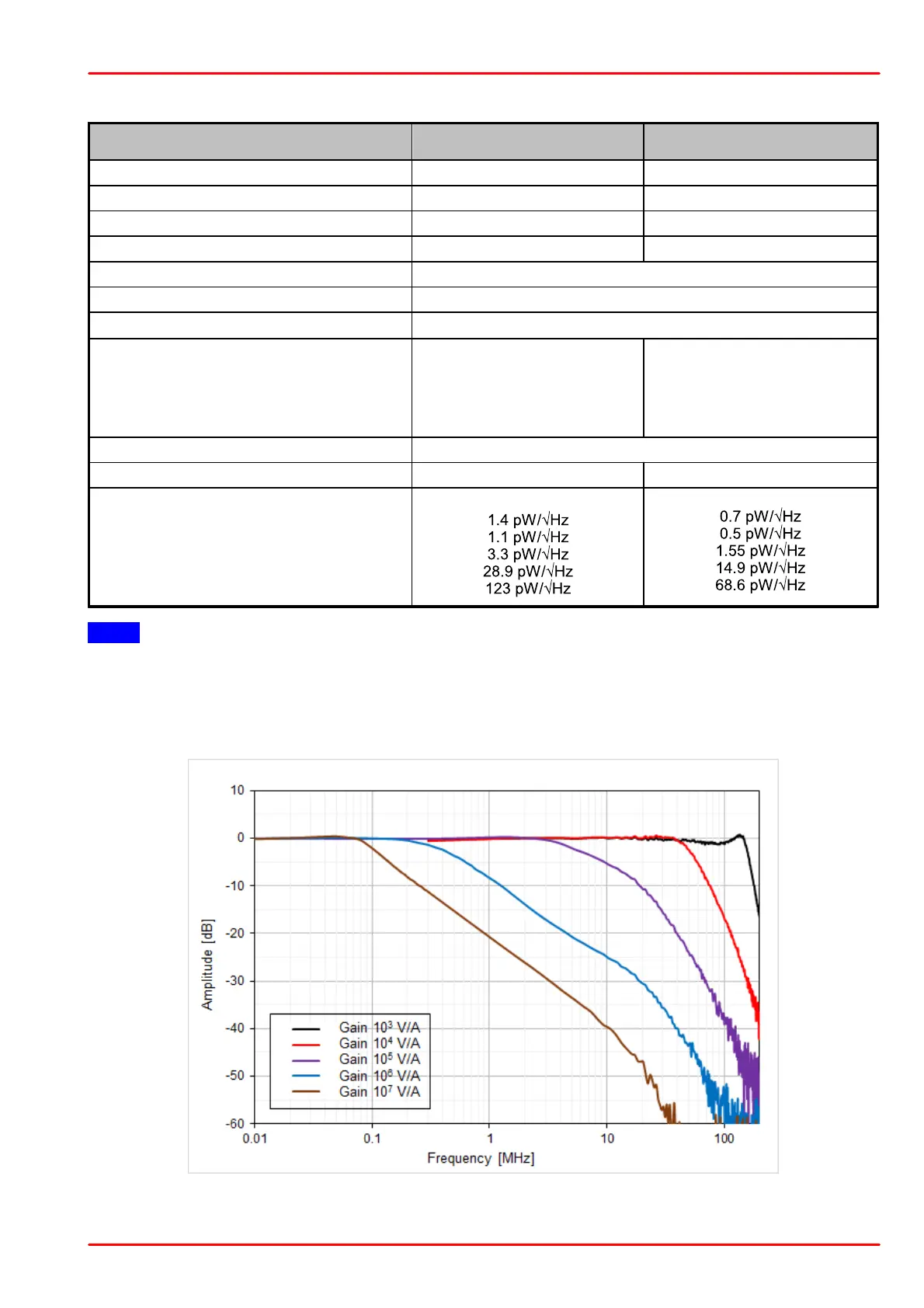
PDB450A: Typical RF OUTPUT Frequency Response
PDB450A: Typical RF OUTPUT Frequency Response at different gain settings