© 2019 Thorlabs4
PDB440x and PDB450x detectors
2 Getting Started
This section is intended to provide information that explains how to quickly set up the PDB440x
and PDB450x detectors Balanced Amplified Photodetectors. More details and advanced fea-
tures are described in further sections.
2.1 Parts List
Inspect the shipping container for damage.
If the shipping container seems to be damaged, keep it until you have inspected the contents
and you have inspected the item mechanically and electrically.
Verify that you have received the following items within the package:
1. PDB440x or PDB450x Balanced Amplified Photodetector
2. Adapter Plate with four M2x8 screws and a hex key 1.5, for post-mounting the unit on a
optical table
3. LDS12B power supply (±12V, 250 mA), switchable to 100 V, 120 V, or 230 V line voltage
4. Operation manual
2.2 Preparation
Note
Prior to operation, please check, if the indicated line voltage range on the power supply
matches with your local mains voltage! If you want use your own power supply, Thorlabs offers
an appropriate power connector cable.
· Carefully unpack the unit and accessories. If any damage is noticed, do not use the unit
and contact Thorlabs .
· Mount the unit on your optical table or application. Please see the chapter mounting for
detailed information.
· If necessary, mount external optics, filters, apertures or fiber adapters.
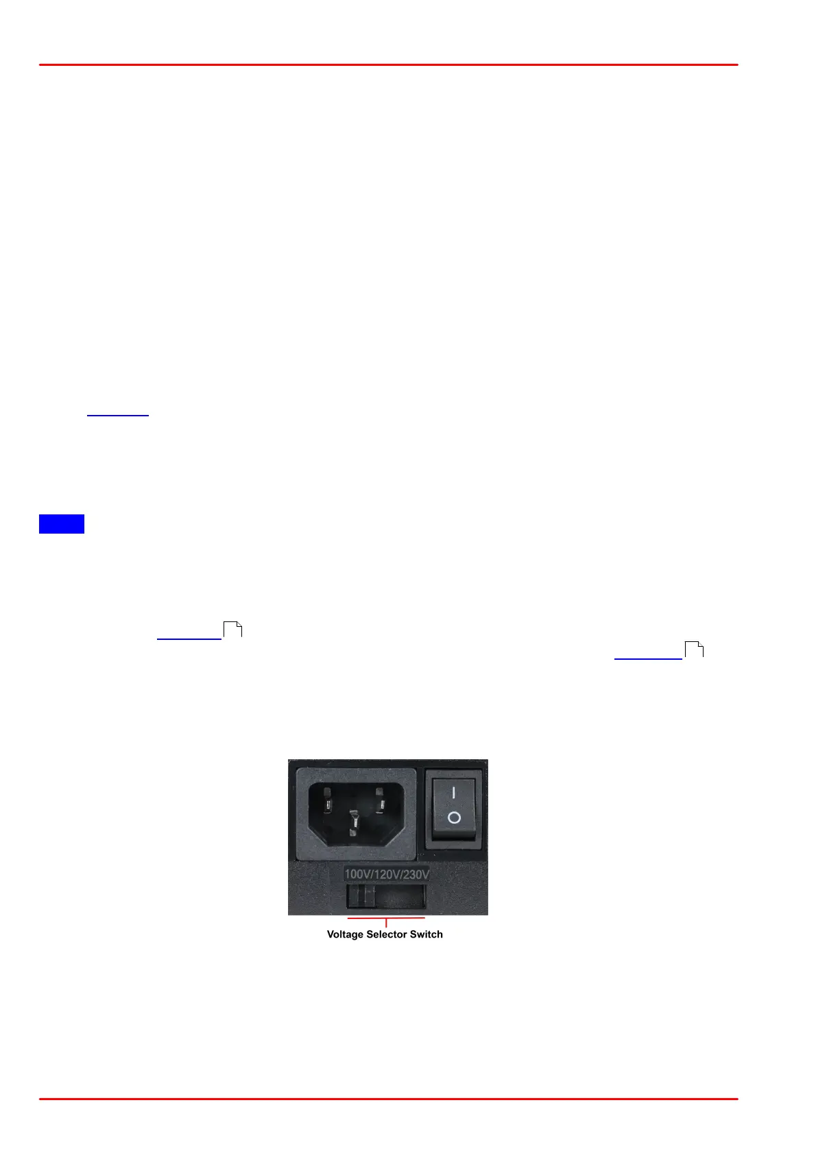
· Adjust the power supply to accommodate your local mains voltage (100 VAC, 120 VAC, or
230 VAC):
· Connect the DC output cable of the power supply to the Power IN jack (DC INPUT).
· Plug the power supply into a 50-60 Hz, 100 VAC, 120 VAC, or 230 VAC outlet.
· Switch on the power supply.
· Connect RF OUTPUT to your data acquisition device using a coaxial cable.
· If desired, connect the monitor outputs (MONITOR+, MONITOR-) to measure the optical in-
put power for each channel individually.
26
9