5 Appendix
Rev: 1.0, 15-Mar-2021
Page 20
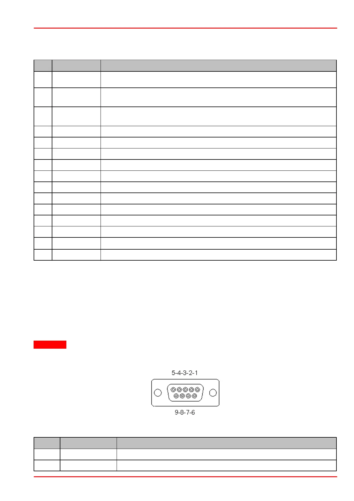
5.2 Pin Assignment Output Connector
PM103: PM103 has a universal DA-15 connector. The Pins are assigned as follows:
Pin for Alternative Power Supply with 5 VDC to 36 VDC, when not
powered by USB
General Digital Input / Output port; 3 V logic (Output), 5 V tolerant for In-
put
General Digital Input / Output port; 3 V logic (Output), 5 V tolerant for In-
put
Analog Output; -0.25 V to +2.5 V per Measurement Range
Software Configurable Analog Output; 0 V to 2.5 V
RS232; Connect to PC terminal RxD (PC DE-9 Pin2)
RS232; Connect to PC terminal TxD (PC DE-9 Pin3)
NTC Thermistor Input; Measurement Range 0.1 kW to 100 kW
RS232 Signal Ground; Connect to PC Terminal Ground (PC DS-9 Pin5)
5.3 Pin Assignment of the Sensor Connector
The sensor connector allows the access of all Thorlabs “C-type" photodiode and pyroelectric
sensors. The power meter interface uses the sensor calibration data, stored in the sensor con-
nector, to calculate the corresponding actual power levels.
Additionally, the PM103x is capable to support custom made detectors. Please read the follow-
ing instruction prior to connecting a self made sensor.
Warning
Pin 2 is uniquely used for the EEPROM Digital I/O (memory in Thorlabs sensor heads) and
MUST NOT be used. Connecting this Pin may cause malfunction of the PM103x.
Pin-out of the DE-9 female
connector (female)
+5 V; Max Current 50 mA from this Pin
Sensor Memory for the Calibration Data
 Loading...