EQUIPMENT: T1216W-C
PUBLICATION: MARINEW-P-I
ISSUE No. & DATE: 1 11/12
© 2012 Thorn Security Ltd PAGE 33 of 39
Registered Company: Thorn Security Ltd. Registered Office: Dunhams Lane Letchworth Garden City Hertfordshire SG6 1BE
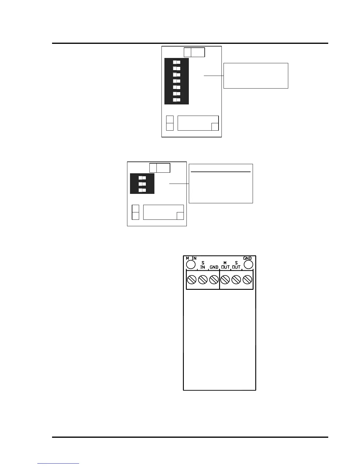
LED 0
S/C 1
S/C 0
F/P 1
F/P 0
1 2 3 4 5
6
LED 1
7
VDR
Configuration Switch
to set quantity & type
of modules connected.
Configuration switches to set
quantity and type of O/P
modules connected.
From top to bottom:
F/P0 – Fire Protection
F/P1 – Fire Protection
S/C0 – Sounder Controller
S/C1 – Sounder controller
LED0 – LED driver
LED1 – LED driver
VDR – Voyage Data Recorder
Figure 13 – C1630 Output Expansion Interface
R2
R1
R0
1 2 3
Configuration Switch
Panel: Sets number of
repeaters.
Repeater: Sets
repeater address.
Figure 14 – C1631 Repeater Interface Board
Field wiring terminals:
M IN – Muster signal in
S IN – Silence signal in
GND – Common 0V
M OUT – Muster signal out
S OUT - Silence signal out
GND - Common 0V
Figure 15 – C1665 Muster Interface Board
 Loading...