EQUIPMENT: T1216W-C
PUBLICATION: MARINEW-P-I
ISSUE No. & DATE: 1 11/12
© 2012 Thorn Security Ltd PAGE 37 of 39
Registered Company: Thorn Security Ltd. Registered Office: Dunhams Lane Letchworth Garden City Hertfordshire SG6 1BE
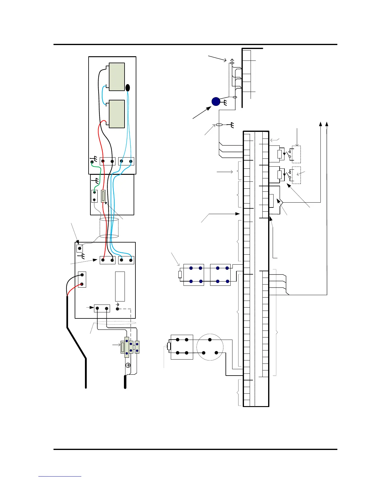
Battery leads supplied
in panel fixing kit
Tie wrap Thermistor to
battery lead above battery
Batt -
Thermistor
+ - + -
Battery Battery
Batt +
T1200B-C Battery Box
Thermistor
Close-coupled
Junction box
(not supplied)
4-core
cable with
Shield
T6.3A HRC
FUSE
Earth Stud
1 3
1A
3A
Zone O/Ps
1 2 3 4
Zone Circuits
Zone Circuits
Alarm Circuits
Aux DC
Inputs Outputs
A
B
Fault
Routing
Aux DC
Fire Routing
Fire
Protection
N/C
RST
GND
Repeater
BAct
EvacDis
Cl/C
RSTEvac
Sil
0V
24V4 -4 +3 +2 +1 + 3 -2 -1 -8
-
8 +7
-
6
-
5 -4 -
3 -
2 -
1 -
1 + 2 +
3 +
4 +
5
+
6 + 7 +
RST
N/OPO/-PC/+O/-
PC/+
C/-
PO/+
0V
24V9 +
10 + 11 +
12 + 13 +
14 + 15 +
16 +
16 -9 - 10 - 11 - 12 - 13 - 14 - 15 -
+
+
-
-
+
+
-
-
L1
L2
L
C1627wiring
terminals
+ -
B
A
GND
A
B
N/C
RST
GND
Repeater
B
A
GND
10k
end-of-line
resistor
Typical Zone Wiring
Zone 1
Typical Alarm
Circuit Wiring
Alarm Circuit 1
Open collector zone O/Ps
[zones 1 to 4]
each 50mA, 30Vdc max.
Connect return to Aux 24V
Zones 2-8
10k end of line
resistor
Zones 9-16
10k end of line resistor
Field wiring terminals on panel PCB
Detector
base
Manual
Call Point
Sounder
3k9
end-of-line
resistor
Aux 24Vdc
supply
See note 2
Aux 24Vdc
supply
See note 2
Alarm Circuits 2-4
Max O/P 1 Amp
each.
3k9 end of line
resistor
Remote O/Ps
See Note 5
Remote I/Ps
See Note 4
Remote Relays
See Note 3
Fire, Fault
Signalling & Fire
Protection outputs
See Note 6
Fire panel
screen earth
terminal block
Fault Signal to Watermist panel
Zones 15 & 16 to Watermist Panel
Remote
indicating
equipment
Remote fire
protection
equipment
Reset relay
Contact rating:
1A at 30Vdc
Repeater
terminals in
optional
Repeater panel
5 x repeaters max
To Repeater A, B & GND
terminals in next repeater.
Screen is Earthed at Panel &
repeaters
Link Screen
Through
Earth Stud in
Repeater
L
E
N
Ship's supply in
[110/230VAc 50Hz]
Direct or via AC
change over unit
Mains fuse
Mains terminal block
on panel chassis
Batt +
Batt -
Thermistor
L
N
Pre-wired
Power Supply
Unit terminals
Battery & Thermistor
terminals
On Chassis
Panel PSU
Connections
24V
0V
24Vdc Output
On Motherboard
24Vdc Output to AC
change over unit
Earth Bar
T1216W-C Panel
 Loading...