EasyManua.ls Logo

Thule Parkway 958 User Manual

Thule Parkway 958
5 pages
To Next Page IconTo Next Page
Page #1 background imageLoading...
Page #1 background image
501550902_02
PARKWAY (4 BIKE / 2 BIKE) 956/957/958
PARTS INCLUDED
pa
rt description
pa
rt
nu
mber
95
6
qt
y.
95
7
/ 95
8
qt
y.
A
upright/bike arm assembly 1
B stinger 1
C
M10 washer 951-1122-54 2 2
D
3/8" lock nut 853-5779 1 1
E 3/8" hex screw 853-5778 1 1
F M12 lock washer 956-1221-59 1 1
G M12 x 40 receiver bolt 908-1240-54 1 1
H
M12 washer 951-1224-54 1 1
I
M8 hex bolt 908-0870-54 1 1
J M8 washer 951-0816-54 2 2
K M8 lock nut 938-0800-54 1 1
L cradle 853-7887 8 4
M
cradle strap 852-3006-001 8 4
N
(4 bike) strap 753-2030-07 1
O (2 bike) strap 753-2030-08 1
Socket wrench with 13mm (1/2"), 14mm (9/16"),
19mm (3/4") sockets and an adjustable wrench (6" or
larger) or 13mm (1/2"), 14mm (9/16"), 19mm (3/4")
wrench and an adjustable wrench (6" or larger)
TOOLS REQUIRED
M
N
O
H
K
GF
J
I
E
DC
BA
L
No more than 4 bicyc
les should be carried on the
4 bike model Parkway.
No more than 2 bicycles should be carried on the 2
bike model Parkway.
Check tightness of all bolts and knobs periodically.
Not intended for off-road use.
Check straps for wear and replace if worn.
Not intended for tandems or recumbents.
Your vehicle must be equipped with a 2" or 1 1/4"
receiver hitch.
Do not install on a trailer or other towed vehicle.

Other manuals for Thule Parkway 958

Question and Answer IconNeed help?

Do you have a question about the Thule Parkway 958 and is the answer not in the manual?

Thule Parkway 958 Specifications

General IconGeneral
MaterialSteel
Maximum Bike Weight35 lbs per bike
FoldableYes
Mount TypeHitch
Hitch Receiver Size2 inches
TiltableYes

Summary

Parkway Bike Rack Components and Tools

Parts Included

Lists all components included in the Parkway bike rack kit with part numbers and quantities.

Tools Required for Installation

Specifies the necessary socket wrenches, wrenches, and adjustable wrenches for assembly.

Parkway Bike Rack Assembly

Step 1: Position Stinger

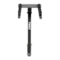
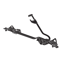
Position the stinger into the cradle of the upper assembly as shown.

Step 2: Secure Upper Assembly

Assemble M8 bolt, washers, and nut; tighten firmly and insert safety pin.

Step 3: Mount to Vehicle

Slide hitch into receiver, align holes, and secure with M12 bolt, washer, and lock nut.

Step 4: Attach Bike Arm Assembly

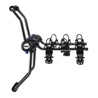
Position bike arm assembly upright and secure with 3/8" screw, M10 washers, and lock nut.

Step 5: Install Cradle Straps

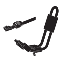
Install the straps onto the hooks of the cradles securely.

Step 6: Load Bicycles

Load the heaviest bike first onto inner cradles, alternating directions.

Step 7: Secure Bikes to Post

Use the provided load strap to secure all bikes to the main post.

Step 8: Lower Carrier for Access

Remove bikes, hold assembly, release safety hook, and slide pin to lower.

Step 9: Lower Carrier to Stop

Gently lower the carrier to its built-in stop position.

Step 10: Secure Carrier to Hitch

Lock the carrier to the vehicle hitch using a separate locking device.

Step 11: Secure Bikes to Carrier

Lock bikes to the carrier using the built-in locking eye and a cable lock.

Related product manuals