7. Remove the Raptor mechanism then drill a 1.5mm
pilot hole on foot bar. Do not drill through the foot bar.
Next secure the bar with 2x5mm wood screw.
8. Locate and trim the molded marks for the engine
cooling openings at the bottom of the fuselage. Enlarge
the eight pre-drilled pilot holes to 3mm in diameter.
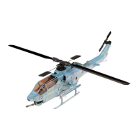
9. Apply foam tape at the mounting area of the landing
skid.
10. Epoxy the exhaust pipe in the fuselage as shown.
11. Drill 2mm (5/64”) holes for antennas at position as
photos shown. Install the antenna and use the retaining
collar to secure the antenna in place. Apply CA on the
collar to prevent it from loose.
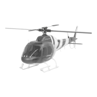
12. Drill the hole on the molded dot. Next enlarge the
hole at about 8mm in diameter. Insert the silicon
grommet in the hole.
13. To install the tail skid in place, first drill 2mm(5/64”)
hole at the bottom fin then secure the tail skid with 2.3x
12mm wood screw. Next drill another 2mm( 5/64”) hole
at the center bottom line about 115mm(4 1/2”) in front
of the bottom fin. Apply epoxy to glue the front end of
tail skid in place.
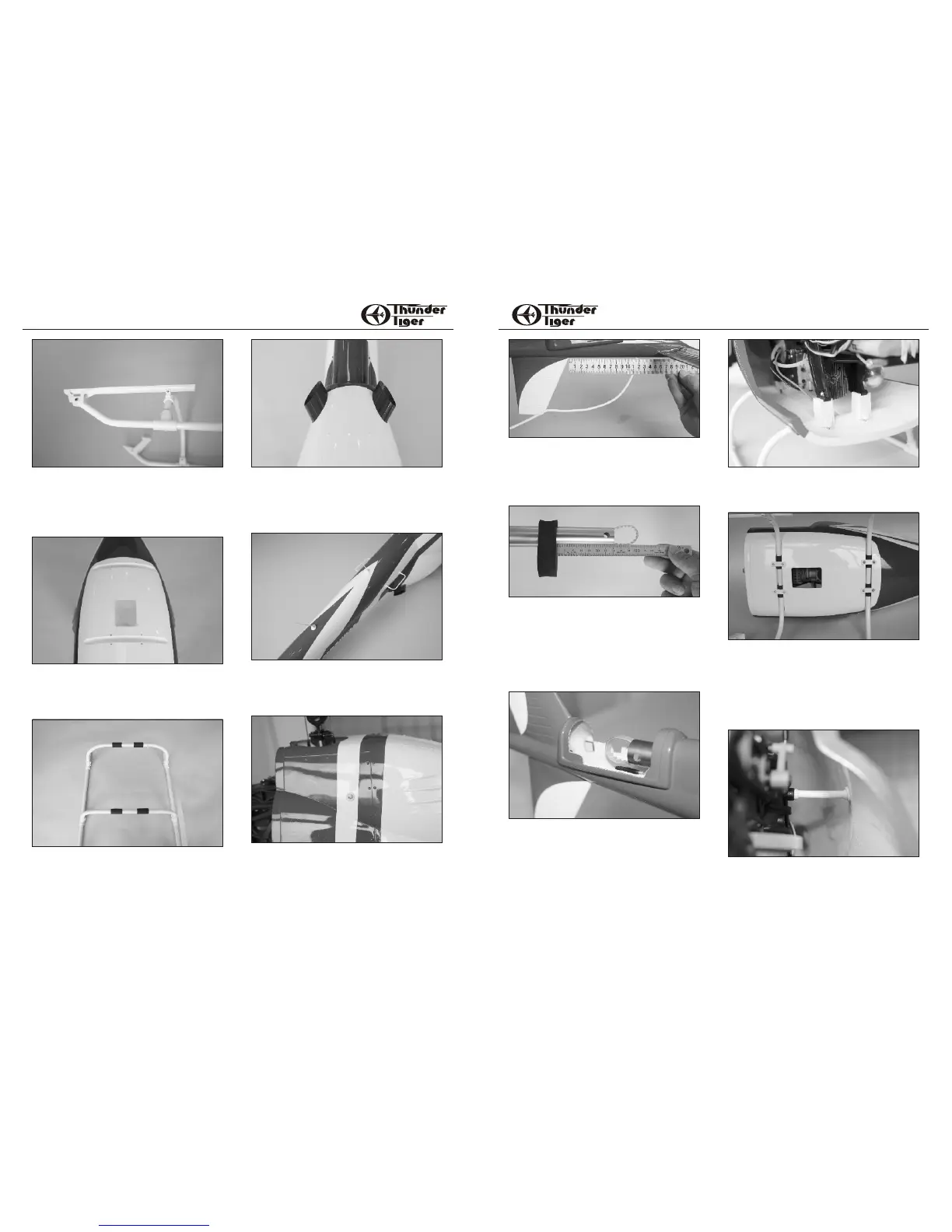
14. Unthread the ball link and install the sponge on the
tail boom section where the plastic tube for the sponge
insertion. CA the tube in the sponge but be careful not
to apply any glue inside the plastic tube and make sure
the pushrod can move freely. Thread the ball link
back to pushrod at the original position. Glue the
sponge on tail boom but make sure the sponge will
tight-fit in the fuselage.
If Raptor 50 Titan is used then the position of sponge
is about 70mm(2-3/4”) to the end of boom.
15. Place the Raptor into the fuselage, the post should
be located near a molded dot on fuselage. Insert the
tail boom into the fuselage and the skid adaptors sit in
place, make sure the sponge is tightly fit in the tail and
secure the tail boom firmly. Check the pushrod
movement is freely without binding and adjust it if
necessary. It is not necessary to glue sponge in the
fuselage in case you had to remove the heli from
fuselage.
16. Before securing the Raptor in place, attach the
foam tape to the contact area of the skid adaptors.
This is to protect the contact area.
17. Attach the landing skid in place then secure with
mounting strip. Note there are three kind of the
mounting strips. Two for from front skid brace and
marked “F”.
For rear skid brace, one for right marked “R-R”, the
rest one is for left side.
Secure the mounting strip in place with the self-
tapping screws. 3x15mm is for the front and 3x20mm
is for the rear.
18. Secure the fuselage with 3x10mm washer self-
tapping screw.
98
ECUREUIL AS355ECUREUIL AS355ECUREUIL AS355ECUREUIL AS355
 Loading...