6
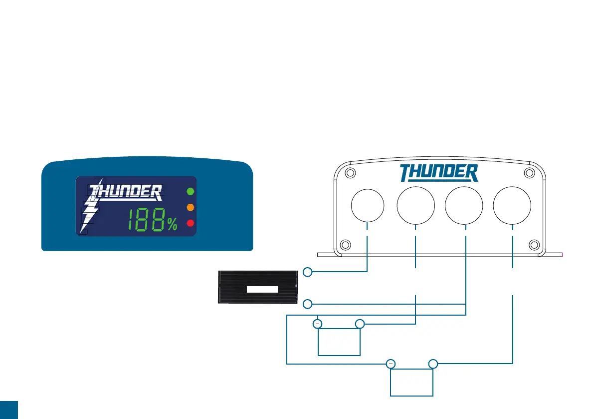
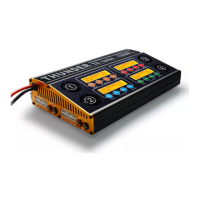
Integrated LED Display & Wiring Diagram
The TDR02010 uses an integrated LED display for easy reference of your
auxiliary battery state of charge and indicator lights.
These functions include;
• Solar (green LED)
• Reverse polarity (orange LED including alarm)
• Faulty battery (red LED)
As your auxiliary battery charges, its state of charge is reflected by the Thunder
logo illuminating in 10% increments. A percentage charge is also shown in green.
This percentage charge will be affected by loads that are attached to the auxiliary
battery. The percentage charge of the auxiliary battery is most accurate when
there is no load being drawn.
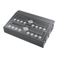
INTEGRATED LED DISPLAY & WIRING DIAGRAM
SOLAR PANEL INPUT DC INPUT
Main
AUX
+
_
NEGATIVE
+
+
DC OUTPUT
Solar Panel
Circuit Breaker
30A Recommended
(Not Supplied)
Circuit Breaker
30A Recommended
(Not Supplied)
REVERSE WARNING
SOLAR INPUT
BATTERY ERROR