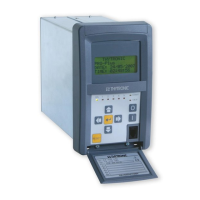
PRON NA60-MB0
Version 3.50
PRON NA60-MB0 Remote Setting Manual
Page: 3 of 59
Introduction
This Protocol Manual is for use with Thytronic Protective Relays, such as the DMC, NTG and PRO-N series that
support Modbus RTU and Modbus TCP communication protocol.
1 Modbus RTU communication
The Thytronic Protective Relay (TPR) uses a communication protocol called Modbus. A company called Modicon,
for use with their programmable controllers, developed the Modbus protocol. Since that time Modbus has evolved
into common communication protocol in industry and it’s now a “de-facto” standard.
The communication method involves using a master-slave technique, in which there is one master and several
slaves. The TPR is a slave device. Only the master can initiate queries. These queries are directed to an individual
slave device and the appropriate slave responds with the requested data.
There are two transmission modes. These modes are known as RTU (Remote Terminal Unit) and ASCII (American
Standard Code for Information Interchange).
The TPR can be setup in a network of up to 247 slave devices. Each device must have a different address (1-247).
The TPR can be set for RTU mode only.
The MODBUS protocol documentation can be found online at www.modicon.com or www.modbus.org
(document “PDI-MBUS-300 REV J”).
1.1 Serial port settings
To communicate with a TPR, the serial port of the Master has to be configured with the following settings:
Address Baud Rate Parity Stop bits Data bits
1 19200 No 1 8
Table 1 Serial port settings
Remark: Every TPR has a default MODBUS Slave Address set to 1.
1.2 Transmission mode
The transmission mode supported by TPR is RTU.
The ASCII transmission mode is not supported.
1.3 Data Types
A TPR has 4 data table, each of which corresponds to one of the 4 basic Modbus data type. Each table contains up
to 1024 data that can be accessed with the proper function as described in the following table.
table/data type reference information Access Function Code for
Reading
Function Code for
Writing
Coils 0X 1 bit Read/Write 0x01 0x05
Discrete Inputs 1X 1 bit Read only 0x02 -
Input Registers 3X 16 bit Word Read only 0x04 -
Holding Registers 4X 16 bit Word Read/Write 0x03 0x06, 0x10
Table 2. Modbus Data Type

 Loading...