INSTALLATION
110
NG10 - Manual - 04 - 2022
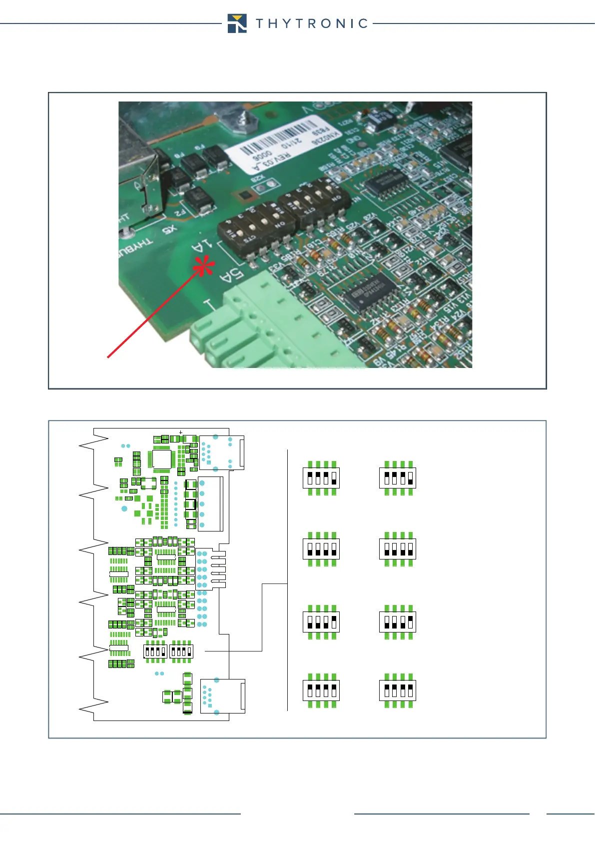
• Set the dip-switches on the right-hand circuit board in accordance with the drawing shown be-
low:
Amperometric inputs 1/5 A
• Move dip-switches according the following layout
• Reassemble all parts with the previous operations in reverse order.
• Reconnect the RS485 and RJ45 cables (Ethernet and/or Thybus).
Dip-switch localization concerning the nominal current setting inside the CPU board
Dip-switch localization concerning the nominal current setting inside the CPU board
Default settings:
- I
nH
= I
nL
= 5 A
- I
En
= 1 A
Setting:
- I
nH
= I
nL
= 5 A
- I
En
= 5 A
Setting:
- I
nH
= I
nL
= 1 A
- I
En
= 1 A
Setting:
- I
nH
= I
nL
= 1 A
- I
En
= 5 A
ETHERNET
THYBUS
485
1 A
5 A
S5
1 2 3 4
IL1H
IL2H
IL3H
IE1
1 A
5 A
S5
1 2 3 4
IL1
IL2
IL3
1 A
5 A
S5
1 2 3 4
IL1
IL2
IL3
1 A
5 A
S5
1 2 3 4
IL1
IL2
IL3
1 A
5 A
S5
1 2 3 4
IL1
IL2
IL3
1 A
5 A
S6
1 2 3 4
IL1
IL2
IL3
IE
1 A
5 A
S5
1 2 3 4
IL1
IL2
IL3
IE
1 A
5 A
SIDE L SIDE H
S6
1 2 3 4
IL1
IL2
IL3
IE
1 A
5 A
S6
1 2 3 4
IL1
IL2
IL3
IE
S6
1 2 3 4
IL1L
IL2L
IL3L
IE2