FUNCTION CHARACTERISTICS
33
NG10 - Manual - 04 - 2022
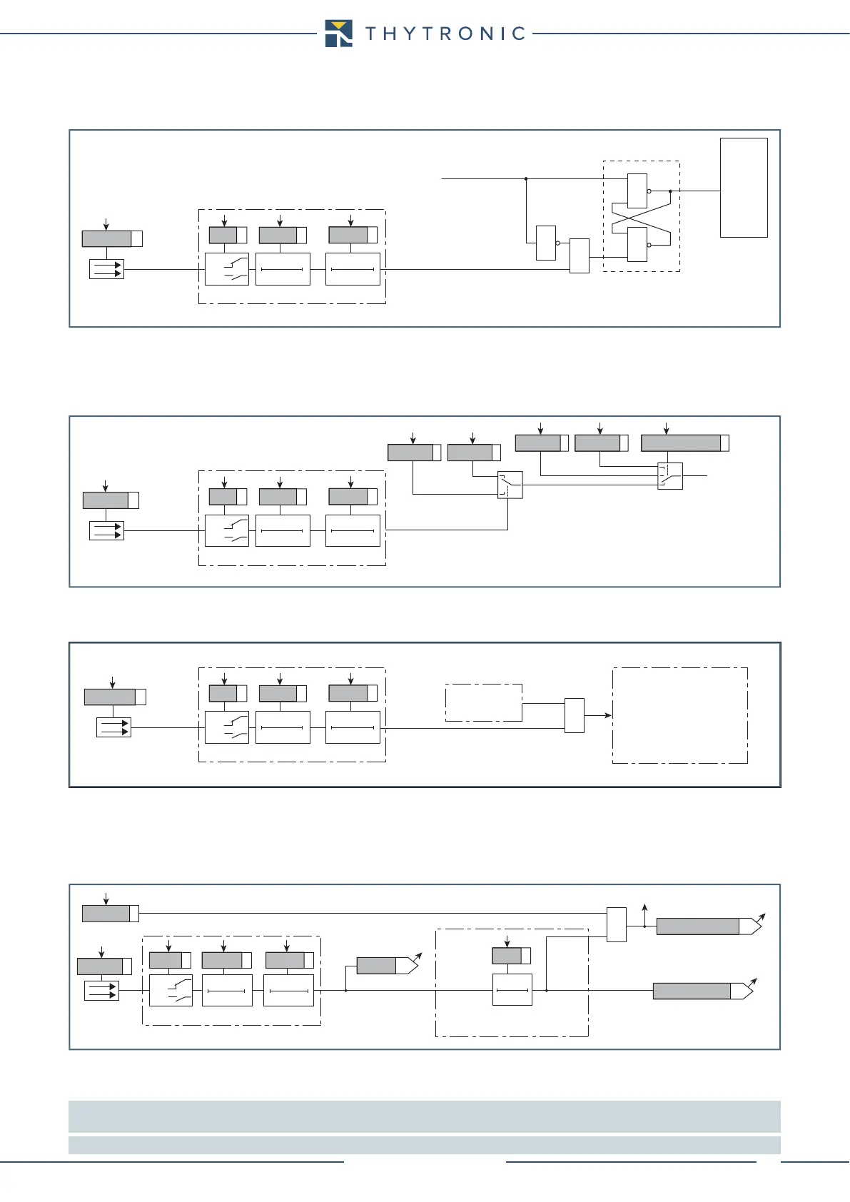
Reset LEDs
If the element tripped have gone back to rest condition, the latched LEDs and/or relays may be
reset.
Set profile
Inside Pro-N devices, two independent setting profiles (A and B) are available. Whereas different
settings are required, they are made in the setting profiles and stored in the non volatile memory of
relay. Applicable setting profile is activated usually via a binary input; when the programmed input is
activated, the profile B becomes operative as a replacement for the default profile A.
[1]
Fault trigger
When the programmed input is activated, a trigger is issued for fault record SFR). Data storing takes
place with the same procedure resulting from a trip of any protective elements.
Block2 IPh/IE
A change in status of a binary input effects a block
[2]
common for the phase and ground protective
elements.
The application of the IN1 and IN2 binary inputs for the acquisition of Block2 (selective block) com-
ing from external protection relays is shown in the following figure (one phase overcurrent and one
phase and residual overcurrent protection).
Note 1 To enable the profile switching the “Input-selected” parameter must be set inside the “Profile selection” submenu.
If multiple setting groups are not required, Group A is the default selection
Note 2 The exhaustive treatment of the Block 2 function is described in the “Logic selectivity” paragraph.
Reset-led.ai
TRIPPING MATRIX
(LED+RELAYS)
≥
≥
&
&
Set (ON≡ turn on LED/relay)
S
Set-Reset latch
R
Reset (ON≡ turn off LED/relay)
Reset LEDs
T 0
INx
t
ON
T0
n.o.
n.c.
INx tON
Logic
INx tOFF
INx
t
OFF
Binary input INx
Binary input allocation for reset signalling (LEDs)
Switch-profile.ai
OFF≡ Profile A, ON≡ Profile B
Profile A
Profile B
Profile A
Profile selection
Profile B
Set profile
T 0
INx
t
ON
T0
n.o.
n.c.
INx tON
Logic
INx tOFF
INx
t
OFF
Binary input INx
Binary input allocation for switching of setting profiles
Trigger-faults.ai
Fault trigger
T 0
INx
t
ON
T0
n.o.
n.c.
INx tON
Logic
INx tOFF
INx
t
OFF
Binary input INx
Fault recording
Protection
element
I
L1H
->I
L1Hr
I
L2H
->I
L2Hr
.....
Inputs
Outputs
Fault cause info
≥ 1
Binary input allocation for fault recorder trigger
Block2H(L)
T 0
t
BH(L)
BlockIph-Ie.ai
t
BH(L)
xxxxx Trip Block2
Block2 input enable (ON≡ Enable)
&
Block2 IN
towards reset timer
Block2H(L) input
Block2 input
FROM ANY PROTECTIONS
Block2
Binary input INx
T 0
Logic
INx
t
ON
INx
t
ON
INx
t
OFF
T0
n.o.
n.c.
INx
t
OFF
Binary input allocation for logic selectivity (Block2)