FUNCTION CHARACTERISTICS
64
NG10 - Manual - 04 - 2022
The operation of the second differential protection threshold (TR I
d
>>) occurs at the instant when the
intervention occurs the threshold in at least one of the L1, L2, L3 phases.
The I
d
>> parameter is available inside the Set \ Profile A(or B) \ Differential 87G-M-L \ Id>> Ele-
ment \ Definite time menu
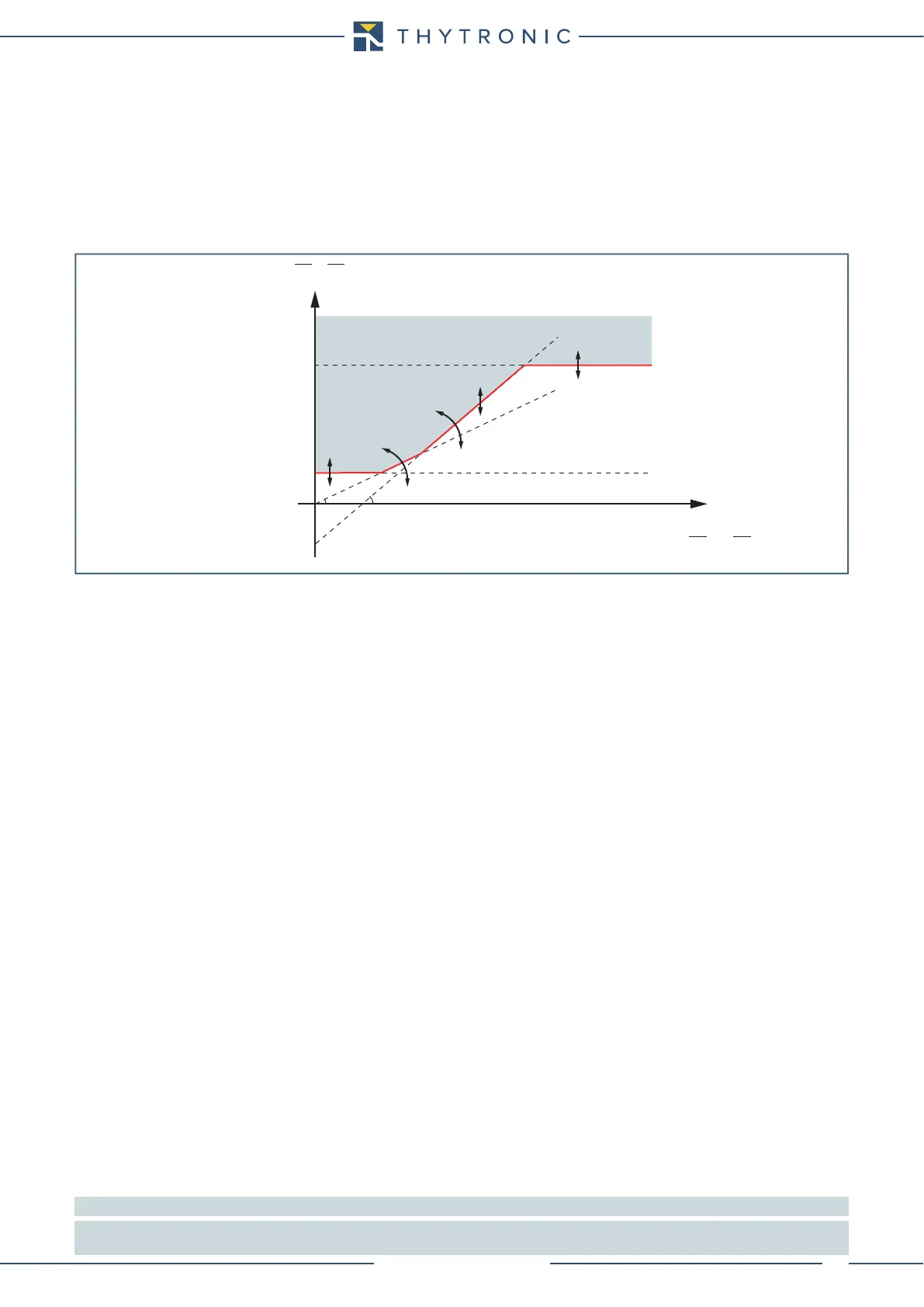
Differential protection is thus stabilized against external faults by increasing the threshold current
differential with increasing current passing through the protected area, according to the following
operating characteristic double slope percentage in the Id-IS plan (where the Id value is the funda-
mental component of the differential current in the L1 or L2 or L3 phases and IS is the fundamental
component of stabilization current in the L1 or L2 or L3 phases).
Breaker failure (BF)
With single enable flag for first or second threshold of differential protection the element can pro-
duce the Breaker Failure if the 87H-M-LBF parameter is set to ON inside the Set \ Profile A(or B) \
Differential - 87G-M-L \ Common configuration.
[1]
The following block criteria are available:
Logical block (Block1)
If the 87G-M-L-BLK1 enabling parameter is set to ON and a binary input is designed for logical
block (Block1), the element is blocked off whenever the given input is active.
[2]
The enabling param-
eters are available inside the Set \ Profile A(or B) \ Differential - 87G-M-L \ Common configuration
menu, while the Block1 function must be assigned to the selected binary input inside the Set \
Inputs \ Binary input IN1(x) menus.
Selective block (Block2)
With single enable flag for first or second threshold of differential protection the element can pro-
duce the output block (committed pilot wire or output relay) programmed for logic selectivity if the
87G-M-LBLK2OUT parameter is set to ON inside the Set \ Profile A(or B) \ Differential - 87G-M-L
\ Common configuration menu.
The logic selectivity function may be performed by means any combination of the following I/O:
• One committed pilot wire output (BLOUT1).
• One or more output relays designed for output selective block.
Only when the committed pilot wire are used the continuity check of the pilot wire link is active.
Use of committed pilot wire output BLOUT1:
• The information about phase or phase+earth block may be select programming the ModeBLOUT1
parameter (OFF-ONIPh-ONIPh/IE-ONIE) inside Set \ Profile A(or B) \ Selective block-
BLOCK2 \ Selective block OUT menus.
Use of output relay (K1...K6):
• If the 87G-M-L-BLK2OUT enable parameter is set to ON and a output relay is designed for selec-
tive block (Block2), the protection issues a block output by phase elements (BLK2OUT-Iph) or by
any protection element (BLK2OUT-Iph/IE), whenever the given element (Start 87G-M-L) becomes
active, while the BLK2OUT-Iph-K,BLK2OUT-Iph/IE-Kand/or BLK2OUT-IE-Koutput relays
and LEDs (BLK2OUT-Iph-L,BLK2OUT-Iph/IE-Le/o BLK2OUT-IE-L) must be select inside the
Set \ Profile A(or B) \ Selective block-BLOCK2 \ Selective block OUT menu.
Note 1 The common settings concerning the Breaker failure protection are adjustable inside the Breaker Failure - BF menu.
Note 2 The exhaustive treatment of the logical block (Block 1) function may be found in the “Logic Block” paragraph inside CONTROL AND MONITOR-
ING section
NO TRIP
TRIP
I
s
I
d
I
d
>
I
d1
=(K2/100) ∙ I
S
-Q
I
d1
=(K1/100) ∙ I
S
I
d
=|I
Lc(H)
- I
Lc(L)
|
0
-Q
2
1
I
d
>>
I
S
=[|I
Lc(H)
| + |I
Lc(L)
|]/2