with PSK31 using DigiPan or a similar program. PSK31
(also called BPSK31) is probably the easiest mode to operate
and it works great with low power. The 20 meter PSK31
frequency of 14.070MHz is usually the most active
frequency. Set your radio to USB (or USB-Data if needed),
select a wide filter (~2.7Khz) and be sure all noise reduction
is turned OFF. Please take some time to read your
communication program's documentation and seek help
from an online source or a fellow Ham if you need help
getting started. If you experience a problem with the
SignaLink USB, then please see the “Troubleshooting”
section at the end of this manual.
- SIGNALINK CONTROLS AND INDICATORS -
PWR Switch – This turns power ON/OFF to the SignaLink's
Transmit and Receive circuits, but it does not power down the
built-in sound card. The SignaLink's sound card will power
down automatically with the computer when the computer is
shutdown, or put into “suspend” mode. We normally suggest
that you turn the SignaLink OFF when it's not in use.
PWR LED – This LED will be ON when the computer is
powered up and the SignaLink’s “PWR” switch is depressed.
Note that if the computer enters “suspend” mode and shuts
off power to the USB port, then this LED will turn OFF even
if the SignaLink’s power switch is turned ON.
PTT LED – This LED is ON only when the SignaLink is
transmitting.
TX Control – This knob adjusts the Transmit Audio level
going to the radio, which directly affects the radio’s RF
power output level during SSB/Data-SSB operation. Turn
this knob clockwise for more power and counter-clockwise
for less. The radio's RF Power control should typically be
set to 100% full power and then the SignaLink's TX knob is
adjusted until the desired RF power level is measured on a
watt meter or the radio's Power Output meter function.
NOTE: When operating with FM modulation (VHF/UHF
1200 baud Packet, EchoLink, etc.), the TX knob affects
deviation, not RF power. Set the radio for the desired power
level using the radio's RF Power setting and then adjust the
TX knob until a clean signal is heard on a nearby radio.
RX Control – This knob adjusts the Receive Audio level
that is displayed in your communication program's waterfall
or spectrum display. Turn this knob clockwise for more
audio and counter-clockwise for less. 50% is a good starting
point. Most programs have a level indicator that shows
when the program has adequate audio.
DLY Control – This knob adjusts the Transmit “Hang Time”
for the SignaLink USB’s Auto-PTT
TM
circuit. With the DLY
knob set to minimum (fully counter-clockwise), the radio will
remain keyed for approximately 28 ms after Transmit Audio
has stopped. This setting is suitable for modes that require
fast turn-around times like Packet. It is also the best position
for most other digital modes like PSK31. A longer delay of up
to 3 seconds can be selected by turning the control clock-wise.
A delay of approximately 2 seconds is adequate for most
Voice modes such as EchoLink. For slow AFSK CW, you
will usually want a delay of around 500 ms to 1 second.
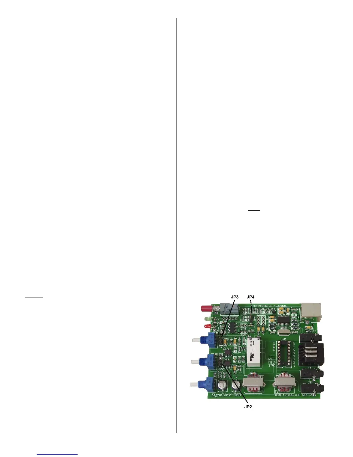
- SPECIAL JUMPERS -
The SignaLink USB has three special jumpers that can be
enabled to provide higher Transmit and Receive Audio
levels, and increase the unit’s PTT sensitivity. These
jumpers are described below and their location is shown in
Figure 10. To enable a jumper, simply remove it from the
single metal pin that it is installed on and then reinstall it
across the two visible metal pins. When removing the
jumper, be sure to pull it straight up. Do not twist it or it
may be damaged.
JP2 – This jumper can be enabled to increase the Receive
Audio signal going into the SignaLink. This affects the audio
level that you see on the waterfall or spectrum display of
your communication program. If you cannot get sufficient
RX Audio by adjusting the SignaLink's RX knob and the
radio's output level control (if available), then you should
enable this jumper.
JP3 – This jumper can be enabled to increase the
SignaLink's Transmit Audio Signal. When enabled, the
SignaLink USB can provide up to 2Vp-p into 600 ohms.
Note that this jumper is NOT needed for most radios. If
you are unable to get sufficient RF power output, then please
check the “Troubleshooting” section at the end of this
manual before enabling this jumper.
JP4 – This jumper can be enabled to increase the sensitivity
of the SignaLink USB’s Auto-PTT
TM
circuit. This is not
necessary for Data modes, but it can offer increased
performance for voice applications by minimizing issues
where the radio's RX/TX switching time causes the first part
of a voice transmission to be cut off.
Figure 10 – Location of jumpers JP2, JP3 and JP4.
 Loading...