5. Set up
IMPORT
ANT
3())
*ÿ+(,)
ÿ
-'./ÿÿ01/ÿÿÿ233#ÿ !3ÿ!4ÿ/#ÿÿ
!4/ÿ52!6'ÿ78ÿÿ1/'
9'2ÿÿ!4ÿ!//%16ÿÿÿ1#! &ÿ!4ÿ32ÿÿ
233#ÿ !3ÿ:#ÿ'ÿ8ÿÿ !3ÿ/ 2#6'ÿ
INST
ALLING CUTTING ATTACHMENT GUARD
• Put the cutting attachment guard on the gearbox, at-
tach it with the 2 screws and hardware provided.
8
BRU
SH CUTTER AND EDGE TRIMMER
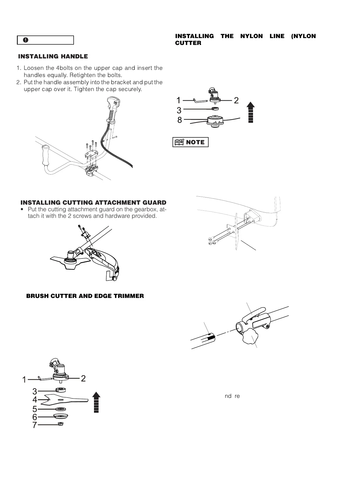
INSTALLING THE NYLON LINE (NYLON
CUTTER HEAD)
INST
ALLING METAL BLADE
1
- Place the collar rin
(
3) on the shaft thread.
2- Insert the key wrench (1) into the
ea
r
case lockin
hole
.
3- Secure metal blade (4) between collar rin
(3)
a
nd washer (5).
4- Place the washer (6)
5- Screw the nut (7).
1- key ;
2-
ea
r case ;
3- collar rin
;
4-
metal blade;
5- washer;
6- washer;
7- nut
1- Place the collar rin
(
3) on the shaft thread.
2- Insert the key wrench (1) into the
ea
r case
lockin
ho
le.
3- Screw the nylon spool (8) on the shaft thread.
4- Check the spool is secured ti
htl
y
1- Key ;
2-
ea
r case ;
3-collar rin
;
8-
nylon spool
Before using trimmer head, mount the trimming knife with
3 screws as illustrated below. When the machine is run-
ning, tap the trimmer head on the ground, the trimmer line
will come out automatically. The trimming knife will cut and
keep the trimmer line in correct length.
Trimming knife
•
CONNECTINHG THE SHAFT
A
B
C
T
o connect the working shaft to the main
shaft,
Loose the turnin
nu
t(A) and
r
ess the
“Push”button(B).
Insert the workin
s
haft into the
connector and release the “ Push ”
button(B),make sure the “ Push ”
buttons locks the hole (C) on the
workin
shaft.
Se
cure the turnin
nu
t(A).
•
•
GB 6