•
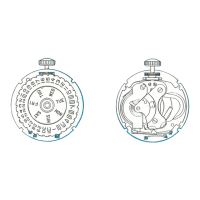
WHEEL
HOUR EEL
Disassembly
of
Movement
Cont'd.
FIGURE
I
FIGURE
2
FRICTION RING
CENTER WHEEL
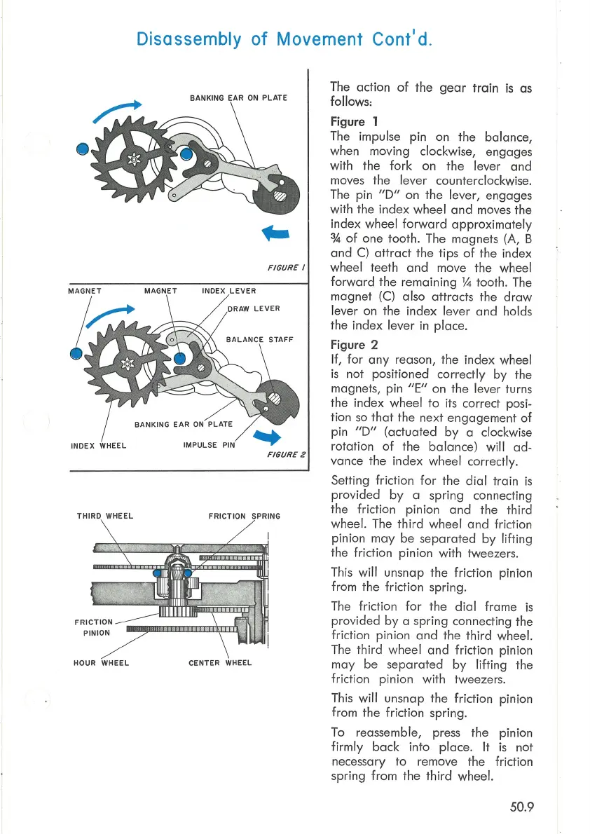
The action
of
the
gear
train
is
as
follows:
Figure
1
The impulse pin on the balance,
when moving clockwise, engages
with the
fork
on the lever and
moves the lever counterclockwise.
The
pin
"D"
on the lever, engages
with the index wheel
and
moves the
index wheel
forward
approximately
%
of
one tooth. The magnets (A, B
and
C)
attract
the tips
of
the index
wheel teeth
and
move the wheel
forward
the remaining
1,4
tooth. The
magnet
(C)
also attracts the
draw
lever on the index lever
and
holds
the index lever in place.
Figure 2
If,
for
any
reason, the index wheel
is
not positioned correctly
by
the
magnets, pin
"E"
on the lever turns
the index wheel
to
its correct posi-
tion
so
that
the next engagement
of
pin
"D"
(actuated
by
a clockwise
rotation
of
the balance) will
ad-
vance the index wheel correctly.
Setting friction
for
the
dial
train
is
provided
by
a spring connecting
the friction pinion
and
the third
wheel. The
third
wheel and friction
pinion
may
be separated
by
lifting
the friction pinion with tweezers.
This will unsnap the friction pinion
from the friction spring.
The
friction
for
the
dial
frame
is
provided
by
a spring connecting the
friction pinion
and
the
third
wheel.
The
third
wheel
and
friction pinion
may be separated
by
lifting the
friction pinion with tweezers.
This
will
unsnap the friction pinion
from the friction spring.
To
reassemble, press the pinion
firmly
back
into place.
It
is
not
necessary
to
remove the friction
spring from the
third
wheel.
50.9