Disassembly
of
Movement
Cont'd.
RETAINING
SPRING
SHUNT
BRIDGE
'""~:,:~'''
~
--------
~
:
.....
I
•
I
I
I
I
I
__
..
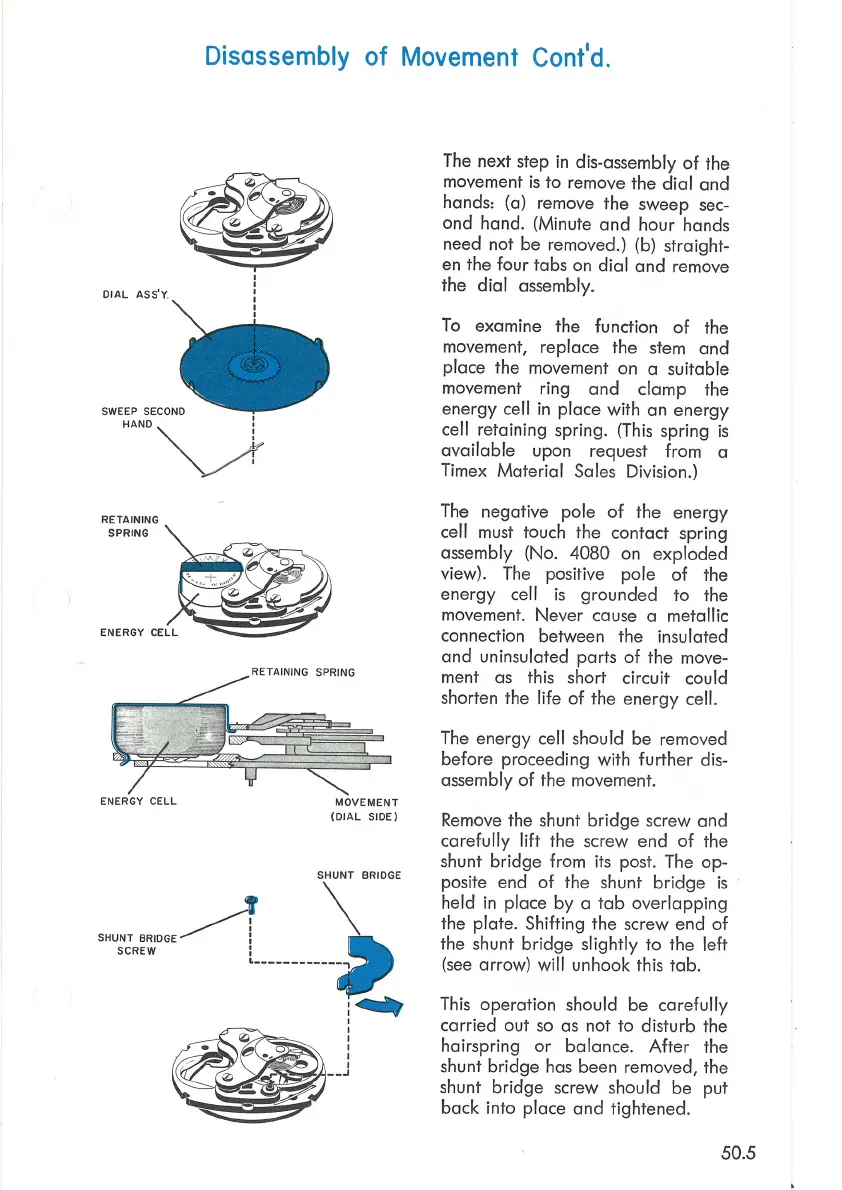
The next step
in
dis-assembly
of
the
movement
is
to remove the
dial
and
hands: (a) remove the sweep
sec-
ond hand. (Minute
and
hour
hands
need not be removed.) (b) straight-
en the four tabs on
dial
and
remove
the
dial
assembly.
To
examine the function
of
the
movement, replace the stem
and
place the movement on a suitable
movement ring
and
clamp the
energy cell
in
place with an energy
cell retaining spring. (This spring
is
available
upon request from a
Timex
Material
Sales
Division.)
The negative pole
of
the energy
cell must touch the contact spring
assembly (No.
4080
on
exploded
view).
The
positive pole
of
the
energy cell
is
grounded
to
the
movement.
Never
cause a metallic
connection between the insulated
and
uninsulated parts
of
the move-
ment
as
this short circuit could
shorten the life
of
the
energy
cell.
The energy cell should be removed
before proceeding with
further
dis-
assembly
of
the movement.
Remove the shunt
bridge
screw and
carefully
lift
the screw end
of
the
shunt
bridge
from its post. The
op-
posite end
of
the shunt
bridge
is
held
in
place
by
a
tab
overlapping
the plate. Shifting the screw end
of
the shunt
bridge
slightly
to
the left
(see
arrow) will unhook this
tab.
This
operation should be
carefully
carried out
so
as
not
to
disturb the
hairspring
or
balance.
After
the
shunt
bridge
has been removed, the
shunt
bridge
screw should be put
back into place
and
tightened.
50.5