DIODE
50.6
Disassembly
of
Movement
Cont•d.
CONTACT PIN
ILLUSTRATION
I
CONTACT
SPRING
ILLUSTRATION
2
ILLUSTRATION
3
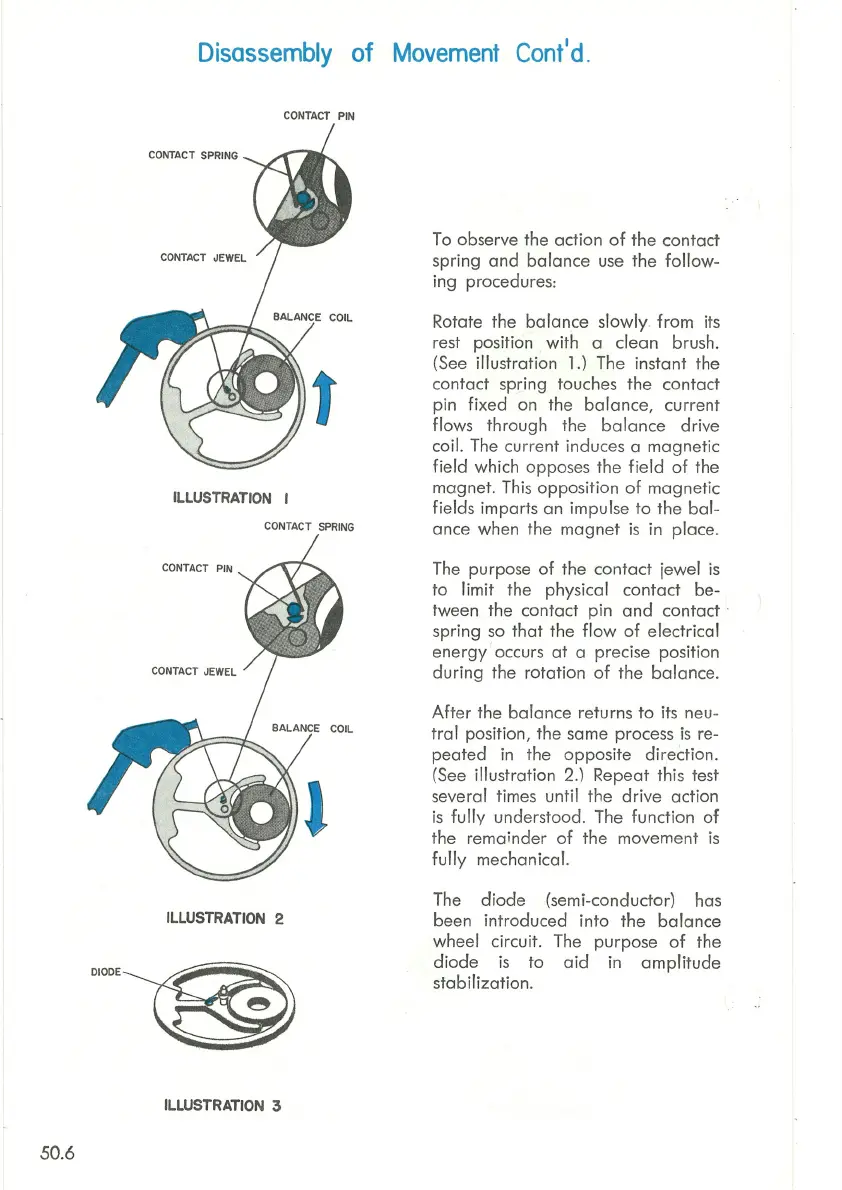
To observe the action
of
the contact
spring
and
balance
use the
follow-
ing procedures:
Rotate the
balance
slowly
.
from
its
rest position
with
a clean brush.
(See illustration 1.) The instant the
contact spring touches the contact
pin
fixed
on the
balance,
current
flows through the
balance
drive
coil. The
cu
rrent induces a magnetic
field
which
oppo
s
es
the
field
of
the
magnet
. This opposition
of
magnetic
fields imparts an impulse
to
the
bal-
ance when the
magnet
is
in place.
The purpose
of
the
contact
jewel
is
to limit the physical
contact
be-
tween the contact pin
and
contact ·
spring
so
that
the
flow
of
electrical
energy
occurs
at
a precise position
during
the rotation
of
the balance.
After
the
balance
returns
to
its neu-
tral
position, the same process
is
re-
peated
in the
opposite
direction.
(See illustration 2.) Repeat this test
several times until the
drive
action
is
fully
understood. The function
of
the remainder
of
the movement
is
fully
mechanical.
The
diode
(semi-conductor) has
been introduced
into
the
balance
wheel circuit. The purpose
of
the
diode
is
to
aid
in
amplitude
stabilization
.