5
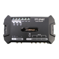
4. POSITIVE POWER CONNECTOR (+BAT): Connect to the posive baery
terminal using a minimum 13 AWG cable. It is recommended to use a 1A
fuse for external protecon.
5. SERVICE CONNECTION: Dedicated connecon for authorized support
services and updates.
6. AUDIO INPUT WITH WIRE CONNECTION (HIGH INPUT): HIGH INPUT type
audio connecon with independent acon (A and B). Check this manual
for the installaon diagram for the radio/player harness.
7. AUDIO INPUT WITH RCA CONNECTION (INPUT): Double type RCA
connectors with independent actuaon (A and B). Connect to the audio
output of the radio/player via RCA cables. Give preference to quality
shielded cables to avoid noise.
8. MAX LEDs (INPUT CHANNELS): These LEDs act individually to indicate
signal saturaon on the input channels.
9. POWER LED / COMMAND BUTTON: Used to reset processor sengs and
updates. See topic “Reset factory sengs”.
10. AUDIO OUTPUTS CHANNELS (OUTPUT): Individual RCA output
connecons provide the audio processed with the parameters
performed in the processor.
11. LIMITER LEDs (OUTPUT CHANNELS): These LEDs actuate when the
“LIMITER” funcon is in use. Each channel has a dedicated LED for
visualizaon of the actuaon individually. The LEDs also act as output
saturaon indicators.
 Loading...