16
E
N
G
L
I
S
H
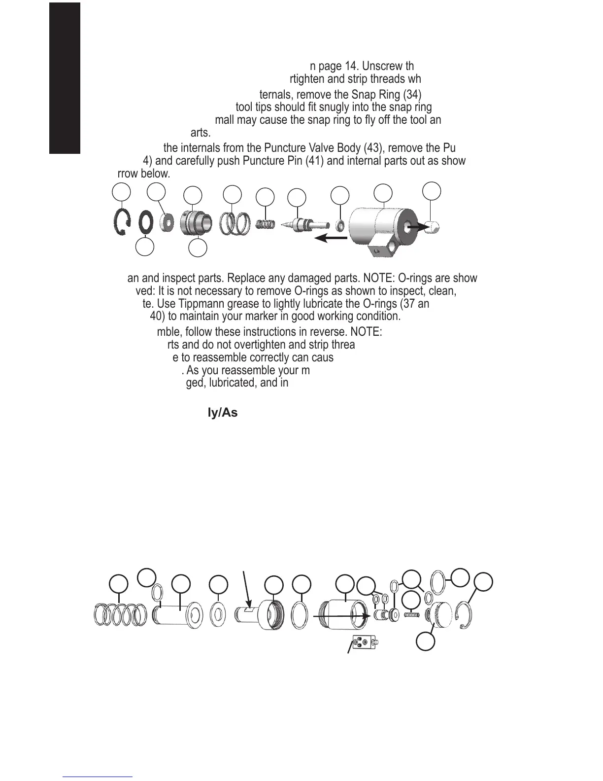
Puncture Valve Disassembly/Assembly
1. Follow Marker Disassembly/Assembly on page 14. Unscrew the Air Fitting from the
open hole in part 43 below. Do not overtighten and strip threads when reassembling.
2. To access the Puncture Valve internals, remove the Snap Ring (34) with a snap ring
tool. NOTE: The snap ring tool tips should t snugly into the snap ring - using a snap
ring tool with tips too small may cause the snap ring to y off the tool and cause injury
and/or damage parts.
To remove the internals from the Puncture Valve Body (43), remove the Puncture Pin
Cap (44) and carefully push Puncture Pin (41) and internal parts out as shown at the
arrow below.
3. Clean and inspect parts. Replace any damaged parts. NOTE: O-rings are shown
removed: It is not necessary to remove O-rings as shown to inspect, clean, and
lubricate. Use Tippmann grease to lightly lubricate the O-rings (37 and 42) and Springs
(39 and 40) to maintain your marker in good working condition.
4. To reassemble, follow these instructions in reverse. NOTE: Carefully hand start all
threaded parts and do not overtighten and strip threaded parts when reassembling.
NOTE: Failure to reassemble correctly can cause damage to parts, air/CO2 leaks, and
other problems. As you reassemble your marker, double check to be sure parts are
clean, not damaged, lubricated, and installed correctly.
Air Valve Disassembly/Assembly
1. Follow Marker Disassembly/Assembly on page 14.
2. Refer to the diagram below. Slide the Front Bolt Spring (52), Front Bolt (54), and
Damper (55) off the Power Tube (56).
3. Remove Power Tube from the Air Valve Body (58) by unscrewing the Power Tube with a
1/2” wrench on the “wrench ats” (see arrow below).
4. To access the Air Valve Body internal parts, remove the Snap Ring (65) with a snap ring
tool. NOTE: The snap ring tool tips should t snugly into the snap ring. Using a snap
ring tool with tips too small may cause the snap ring to y off the tool and cause injury
and/or damaged parts. To remove the internals from the Air Valve body (58), carefully
push them out with a plastic tool in the direction shown.
5. Clean and inspect parts. Replace any damaged parts. NOTE: O-rings are shown
removed. It is not necessary to remove O-rings as shown to inspect, clean, and
lubricate. Use Tippmann grease to lightly lubricate the O-rings (53, 57, 60, 61, and 62)
and springs (52 and 63) to maintain your marker in good working condition.
52 54
53
55
56
57
58
60
61
63
62
65
64
NOTE: The Firing Valve Assembly attaches to the Air
Valve (58) (see Firing Valve Disassembly/Assembly).
44
43
42
41
40
39
34
37
38
35
36