14a
24
NOTE: If the lever cannot be clamped, slightly loosen the nut. If the lever
can be clamped without resistance, tighten the nut.
Adjusting
WARNING! Adjust the guard position according to the intended
operation! The closed side of the guard must always point to the user!
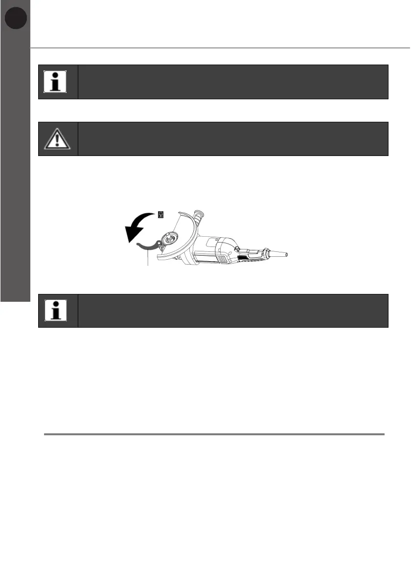
1. Open the clamp lever (14a).
2. Rotate the guard to required position (Fig. 10).
3. Close the clamp lever (14a).
Fig. 10
NOTE: The position of the guard can also be adjusted after the wheel
has been attached.
Removing / replacing
1. Remove the locking flange (10), the wheel and the backing flange (11) (if any).
2. Open the clamp lever (14a).
3. Rotate the guard until the noses on the ring is aligned to the notches on the
spindle collar, and then remove the guard.
4. Attach a new / other guard as described.
Grinding / cutting wheels
With this product different grinding / cutting wheels can be used depending on the
workpiece material.
TTB879GRD by TITAN


 To Next Page