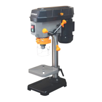
The TITAN TTB924DBT 350W Drill Press is a bench-top drill press designed for drilling holes in wood, MDF, plywood, plastic, and metal. It is intended for normal (non-professional or commercial) household use and should not be used for drilling in stone, concrete, or similar materials. The product is designed to be mounted onto a bench top or similar surface.
Function Description
The drill press is used to create precise holes in various materials. It features a chuck guard for safety, a drill table with height and angle adjustment, and a depth adjustment mechanism for consistent drilling depth. The machine operates in continuous mode and is equipped with a magnetic switch to prevent accidental restarts after a power supply loss.
Important Technical Specifications
- Model Number: TTB924DBT
- Rated Voltage, Frequency: 230-240 V~, 50 Hz
- Rated Input: 350 W S1 (continuous operation), 500 W S6 40% (intermittent periodic duty)
- Rated No Load Speed (n₀): 1450 min⁻¹
- Spindle Speed: 600-2650 min⁻¹
- Drill Capacity: Ø 1.3 - 13 mm
- Drill Chuck: B16
- Max. Drill Depth: 50 mm
- Drill Table Tilting Range: 0° - ±45°
- Drill Table Dimensions: 160 x 160 mm
- Protection Type: IPX0
- Weight: Approx. 13.6 kg
- Dimensions: Approx. 420 x 210 x 600 mm
- Sound Pressure Level (LPA): 70.8 dB (A)
- Sound Power Level (LWA): 83.8 dB (A)
- Hand Arm Vibration (ah,w): < 2.5 m/s²
The S1 operation mode (continuous operation) means the motor can be operated continuously at its 350W power level. The S6 40% operation mode (intermittent periodic duty) indicates that the motor can be operated continuously at its nominal power level of 500W for no longer than 4 minutes. Exceeding this time limit can cause the motor to overheat. During the no-load running period, the motor will cool to its starting temperature.
Usage Features
- Assembly: The drill press requires full assembly before operation. It is crucial to follow the step-by-step instructions and use the provided pictures as a visual guide. The machine must not be connected to the power supply until fully assembled. Small parts removed during assembly or adjustments should be kept secure to avoid loss.
- Bench Mounting: The base (11) has two mounting holes (11b) for securing the product to a level, horizontal bench or work table using two mounting sets (not provided).
- Power Connection: Before connecting to power, ensure the green On button (18) is not pressed. The voltage must comply with the rating label information.
- Feed Handles: The three feed handles (7) are screwed clockwise onto the spindle feed head (16).
- Chuck Guard (14): The chuck guard is pre-assembled and must be properly installed and functioning before operation. Its height can be adjusted based on the drill bit length and workpiece. The depth scale (20) passes through a ring hole (6c) on the machine head (6). The crosshead bolt (14b) and wing nut (14e) allow for adjustment and securing of the guard. The red pointer (20b) should be aligned with the "0" mark on the scale meter (20a).
- Drill Chuck (15): Before assembly, all mating surfaces of the drill chuck and spindle (6b) must be cleaned of oil or grease to prevent loosening during operation. The chuck is assembled onto the spindle (6d) by lowering it with the feed handles (7) and applying downward pressure. A scrap piece of wood should be placed on the drill table (13) during this process. To remove the chuck, lower it to its lowest position, place a ball joint separator above it, and tap lightly with a hammer or rubber mallet. The chuck jaws (15a) should be raised fully to avoid damage.
- Drill Table Adjustment:
- Height: Loosen the clamping lever (9a) anticlockwise, adjust the drill table (13) to the desired height, aligning it with the base (12) and machine head (6), then tighten the clamping lever (9a) clockwise.
- Angle: Loosen the hex bolt (13c) anticlockwise underneath the drill table (13) with a 10mm hex key. Tilt the table until the pointer line (13a) aligns with the desired angle on the angle scale (13b), then tighten the hex bolt (13c) clockwise.
- Depth Adjustment: Rotate the feed handle (7) to lower the drill bit to the required depth, aligning the red pointer (20b) with the desired value on the scale meter (20a). The two nuts on the depth scale can be used to set a maximum depth for repeated drilling.
- Speed Adjustment: The drill press speed is adjusted by changing the belt position on the pulleys. This involves loosening the locking knob (1a) and belt tension lock knob (4), opening the pulley cover (1), moving the belt (3) to the desired pulley combination (refer to the speed chart in the manual), pushing the motor unit (5) away from the column (8) to tension the belt, and then tightening the belt tension lock knob (4) and closing the pulley cover (1). The machine is equipped with a safety switch inside the pulley cover (1); if the cover is not assembled correctly, the machine cannot be activated.
- On/Off Switch: The product is switched on by pressing the green ON button (18) and off by pressing the red OFF button (19).
- Drilling Operations: Always clamp the workpiece securely using a vice (not provided); never hold it by hand. Small diameter drills require higher speeds, while larger diameter drills require slower speeds. Pre-drilling larger holes with a smaller bit is recommended. Avoid drilling at top speed constantly to reduce wear. Use a scrap piece of wood under wooden workpieces to prevent tear-up. For drilling into plastic and metal, punch the drilling point first, use a metal drill bit, select a low speed, and use a cooling lubricant if necessary. Never use water or water-based lubricants for cooling to avoid electric shock. When drilling brass and copper, avoid oil as the drill bit may jam.
- Drill Bit Insertion: Fold up the chuck guard (14), insert the chuck key (21) into the drill chuck (15), turn anticlockwise to open the jaws (15a), insert the drill bit all the way to the stop, turn clockwise to fasten, and then fold down the chuck guard. Ensure the drill bit is centered.
- After Use: Switch off the machine, wait for it to stop completely, disconnect from power, and let it cool down before cleaning and storing.
Maintenance Features
- General Cleaning: Keep the machine clean and free of debris. Regular cleaning helps prolong the product's life. Clean air vents with a soft brush to prevent overheating. Do not use chemical, alkaline, abrasive, or aggressive detergents or disinfectants as they may harm surfaces.
- Inspection: Before each use, inspect the machine and accessories for damage or wear. Do not use if damaged. Double-check that accessories and attachments are properly fixed.
- Repair: Repairs and maintenance work should only be performed by a qualified specialist. Do not attempt to repair any parts yourself.
- Storage: Store the machine and its accessories in a dark, dry, frost-free, well-ventilated place, out of reach of children, at temperatures between 10°C and 30°C.
- Power Cord Replacement: If the power supply cord (12) is damaged, it must be replaced by the manufacturer or an authorized service centre to avoid safety hazards.
- UK Plug Replacement: If replacing the fitted plug, follow the wiring code: Blue to Neutral (N or black), Brown to Live (L or red), Green/yellow to Earth (E or ). Never connect live or neutral wires to the earth terminal. Use an approved 13 Amp BS 1363 or BS 1363/A plug and a correctly rated 5A BS 1362 fuse. Consult a qualified electrician if in doubt. If a moulded plug is removed, dispose of it carefully to prevent it from being engaged into a socket.
- Lubrication: Lubricate the spindle if it is dry.
- Belt Tension: Adjust belt tension if there is excessive vibration or noise. The belt should move approximately 10 mm when pressed towards the center.
- Screws/Handles: Tighten any loose screws or handles.