EasyManua.ls Logo

TMT Automation Clifford 400 - User Manual

TMT Automation Clifford 400
28 pages
Print Icon
To Next Page IconTo Next Page
Loading...
Question and Answer IconNeed help?

Do you have a question about the TMT Automation Clifford 400 and is the answer not in the manual?

Summary

UL Classification and Product Usage

Product Usage Classification

Product meets UL 325 standards for Class I Residential use.

Safety Overview

Important Safety Instructions

Crucial safety precautions for gate opener operation and installation.

Before Installation

Entrapment Zone Awareness

Identifies and warns about potential pinch points and gate path.

Installation Phase Safety

During Installation Safety

Safety measures to follow while installing the gate opener.

Pull to Open Installation - Part 1

Pull to Open Installation - Part 2

Pull to Open Installation - Part 3

Push to Open Installation - Part 1

Push to Open Installation - Part 2

Connecting Gate Opener to Control Box

Wiring Gate Opener to Terminals

Matching wire colors to terminal blocks for gate opener connection.

Connecting Power Supply

Connecting Batteries

Installing and wiring two 12V batteries in series for power.

Battery Terminal Connections

Positive and Negative Terminal Wiring

Correctly connecting battery terminals to the control board.

Power Adapter and Solar Panel Setup

Solar Panel Wiring and Connection

Setting Limit Switches

Control Board Configuration

Push;Pull Switch Setting

Setting the direction of gate opening.

Stall Force Dial Adjustment

Adjusting the force required to stall the gate operator.

Control Board Settings and Accessories

Autocllose Dial Setting

Setting the timer for automatic gate closing.

Remote Control Management

Pairing Factory Remotes

Step-by-step guide to pair included remotes.

Advanced Remote and System Functions

Troubleshooting - LED and Power Checks

LED Indicator Meanings

Explains what different LED lights indicate on the control board.

Troubleshooting - Settings and Fuses

Manual Operation Procedures

Disengaging Motor Gear

Steps to disengage the motor for manual gate movement.

Overview

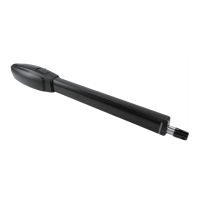
The Clifford 400 is a 24V DC motor swing gate opener designed for residential use. It is classified as a Class I Residential Vehicular Gate Operator, meaning it is intended for use in a home of one to four single-family dwellings, or a garage or parking area associated therewith. The product meets all safety requirements set forth by UL 325 standards.

Technical Specifications:

  • Gear Type: Worm Gear
  • Power Supply: 24V DC
  • Maximum Stroke Distance: 23 inches
  • Maximum Gate Length: 20 feet
  • Maximum Gate Weight: 1000 lbs
  • Operating Temperature: -4°F ~ 122°F

Function Description:

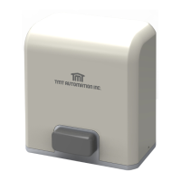
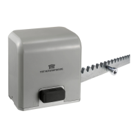
The Clifford 400 automates the opening and closing of swing gates. It can be configured for both "Push-to-Open" and "Pull-to-Open" operations, with settings controlled via a dial on the control board or through the Chow! App (where available). The system incorporates safety features such as a stall mechanism to prevent injury or damage if the gate encounters an obstruction. It supports both single and dual gate setups.

Installation and Setup:

Before installation, ensure the gate is in proper working condition: level, firm, able to swing freely, and self-supporting without wheels. The gate opener is suitable for metal, chain link, tubular, and wrought iron gates, but not recommended for wooden gates or solid surface gates without discretion. Ample space (at least 10 feet in each direction) should be left around the gate's operation area to avoid traffic congestion. Entrapment zones, including the gate's path, pinch points between the operator and gate, and areas between the gate and column post, must be kept clear. The gate opener should always be installed on the inside of the property for security.

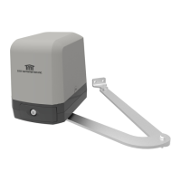
Mounting brackets are assembled from two post brackets and one pivot bracket. The position of the pivot bracket can be adjusted. For pull-to-open installations, the actuator arm extends to open the gate, typically away from the property. For push-to-open installations, the actuator arm retracts to open the gate, typically towards the property. Mounting columns should be robust, with metal or wooden posts at least 3 inches in diameter and set in concrete, or expansion bolts for masonry/brick columns. The gate opener should be mounted near the center of the gate to prevent damage.

The control box and battery box should be mounted at least one foot above the ground to avoid moisture damage and within range of the gate operators. Grounding systems are recommended in areas prone to lightning strikes.

Wiring:

The gate opener connects to the control box via five wires: M+, M-, LMT1, LMT2, and GND. For dual gate openers, a second set of wires connects to M2+, M2-, LMT3, LMT4, S2, GND, and 5V terminals. Wires should be threaded through strain relief and secured, ensuring no exposed strands.

Power Supply:

The system requires two 12V batteries (not included), recommended to be 5Ah. Batteries are connected in series: red wire to Battery 1 positive, black wire to Battery 2 negative, and Battery 1 negative to Battery 2 positive. The BATTERY LED on the control board indicates proper connection; a flashing LED means low voltage.

An AC adapter can also be used. The adapter connects to Power+ and Power- terminals. The POWER LED lights up when the AC adapter is properly connected and the control board is switched ON.

Solar panels can be connected in parallel to charge the batteries. Positive terminals connect to each other, and negative terminals connect to each other. The red wire from the solar panel connects to Power+, and the black wire to Power-. The POWER LED will flash for five seconds upon proper solar panel connection.

Control Board Setup:

The control board features several dials and switches:

  • PUSH/PULL DIAL: Sets the gate opening direction (OFF for Push-to-Open, ON for Pull-to-Open).
  • APP OVERRIDE SWITCH: Allows control of all settings via the Chow! App. When ON, the app has priority; conflicts revert to app settings.
  • STALL FORCE DIAL: Adjusts the force required to trigger the stall mechanism. Turning left sets minimum force, turning right sets maximum force. This should be set in accordance with safety standards and environmental conditions (e.g., high winds).
  • AUTOCLOSE DIAL: Determines the time before the gates close automatically. MIN turns autoclose OFF; MAX sets it to 300 seconds.

Limit Switches:

Limit switches are located under the top cover of the operator. They can be moved to desired positions to initiate gate slowdown before reaching full travel, ensuring smooth and silent operation. Screws must be loosened to adjust and then tightened to secure.

Remote Control Pairing:

To pair factory remotes:

  1. Ensure control board is powered (LED2 ON).
  2. Ensure remote batteries are installed (remove plastic divider).
  3. Press LEARN REMOTE button on control board for 3 seconds (REMOTE LED ON).
  4. Hold RF-Learn button on control board until REMOTE LED lights up.
  5. Press Button 1 on the remote until LED 4 blinks 3 times.
  6. LED 4 turns off, indicating successful learning. Additional remotes can be paired by holding Button 1 and Button 2 together on an already paired remote for five seconds until a click is heard, then pressing any button on the new remote.

Unpairing Remotes:

Hold the LEARN REMOTE button for 10 seconds. The LED will light up, then turn off, indicating all remotes are unpaired.

System Learning:

After pairing at least one remote:

  • Single Gate: Hold Button 2 and Button 3 on the remote simultaneously for 3 seconds until LED 1 turns ON. LED 1 will alternate between 3 seconds ON and 1 second OFF upon successful learning.
  • Dual Gate: Hold Button 2 and Button 4 on the remote simultaneously for 3 seconds until LED 1 turns ON. LED 1 will stay ON upon successful learning. During system learning, do not press any buttons on the remote or control board. If interrupted, LED 1 will flash.

Remote Functions:

  • Button 1: Controls gate opening and closing.
  • Button 2: Pedestrian mode (partially opens gate).
  • Button 3 & 4 (held for 10 seconds): Resets the system to factory settings (LED 1 blinks).

Community Mode:

This mode supports many remotes (up to 50) and prevents command interruptions.

  • To select: Hold Button 3 on a paired remote for 10 seconds (siren beeps twice).
  • To return to normal mode: Hold Button 3 on a paired remote until the siren beeps twice.

Manual Operation:

In emergencies, the operator can be manually disengaged:

  1. Open the cover.
  2. Insert the key clockwise until the motor gear is disengaged (clutch released).
  3. Lift the release fully. To remove the gate operator from mountings:
  4. Remove the hair pin and clevis pin connecting the operator to the mounting bracket.
  5. The gate should then move freely.

Troubleshooting (LED Indicators):

  • POWER LED:
    • ON: Control board properly connected to power (AC adapter or solar panels).
    • OFF: No power connection.
    • Flashing: System learning not completed.
    • Stays ON (after learning): Dual gate learning completed.
    • Alternates with short flashes (after learning): Single gate learning completed.
  • BATTERY LED:
    • ON: Batteries properly connected.
    • Flashing: Batteries have low voltage and need charging.
  • STATUS LED:
    • Flashes for 10 seconds: Successfully connected to sensors.
  • REMOTE LED:
    • Lights up for 10 seconds (after pressing LEARN REMOTE for 3 seconds): Ready to learn remotes.
    • Lights up (when control board receives signal): Remote signal received.

Troubleshooting (General):

  • Fuse Blown: Check the transparent fuse on the control board. If the wire inside is broken, replace it with a backup fuse.
  • APP OVERRIDE Dial: When set to ON, the Chow! App controls settings. When OFF, control board settings take precedence for variables available on the board; otherwise, app settings persist. The Chow! App is not available in the US currently but is expected in late 2023.

TMT Automation Clifford 400 Specifications

General IconGeneral
BrandTMT Automation
ModelClifford 400
CategoryGate Opener
LanguageEnglish

Related product manuals