Do you have a question about the Toa A-903MK2 and is the answer not in the manual?
Explains the process of installing optional plug-in modules into the amplifier's input ports.
Specific instructions for connecting the A-903MK2 model to transformer-balanced speaker outputs.
Specific instructions for connecting the A-903MK2 model to the unbalanced DIRECT output.
Instructions for connecting A-906MK2/A-912MK2 models to transformer-balanced speaker outputs.
Instructions for connecting A-906MK2/A-912MK2 models to the unbalanced DIRECT output.
Details the wiring for the mute control function using external mute and ground terminals.
Describes how to connect a potentiometer for remote master volume control on the front panel.
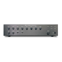
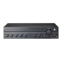
Dimensional diagrams specific to the A-903MK2 model, including width, height, and depth.
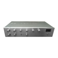
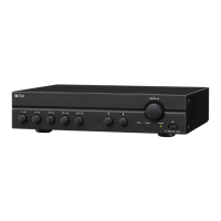
Dimensional diagrams for the A-906MK2 and A-912MK2 models, showing their physical dimensions.
Detailed technical specifications for the A-903MK2 model, covering power, frequency, and inputs.
Detailed technical specifications for the A-906MK2 and A-912MK2 models, including power and frequency.
| Tone Control | Bass: ±10 dB at 100 Hz, Treble: ±10 dB at 10 kHz |
|---|---|
| Power Source | AC 120 V, 60 Hz |
| Frequency Response | 20Hz - 20kHz (±1dB) |
| Total Harmonic Distortion | Less than 0.5%, 1 kHz, rated power |
| Input Sensitivity | Mic: -60 dB, Aux: -20 dB |
| Signal-to-Noise Ratio | 60 dB or more |
| Input | Mic, Aux |
| Output | 4-16 ohms |
| Input Impedance | MIC: 600Ω, AUX: 10 kΩ |
| Output Impedance | 4-16 ohms |
| Phantom Power | Not supported |