EasyManua.ls Logo

Toa BG-1120 User Manual

Toa BG-1120
16 pages
To Next Page IconTo Next Page
Page #1 background imageLoading...
Page #1 background image
MIXER POWER AMPLIFIERS BG-1015
BG-1030
BG-1060
BG-1120
OPERATING INSTRUCTIONS
Thank you for purchasing TOA's Mixer Power Amplifier.
Please carefully follow the instructions in this manual to ensure long, trouble-free use of your equipment.
1. IMPORTANT SAFETY INSTRUCTIONS ..... 2
2. SAFETY PRECAUTIONS ............................ 3
3. GENERAL DESCRIPTION .......................... 5
4. FEATURES .................................................. 5
5. NOMENCLATURE AND FUNCTIONS
Front ............................................................. 6
Rear .............................................................. 7
6. INPUT CONNECTIONS ............................... 8
7. OUTPUT CONNECTIONS ........................... 9
8. PLUG-IN MODULE INPUT PORT
8.1. Module Installation .............................. 10
8.2. Module Selector Switch Settings ......... 10
9. EQUIPMENT SETTINGS
9.1. Mute Function ...................................... 10
9.1.1. Mute operation A ....................... 11
9.1.2. Mute operation B ....................... 11
9.2. TEL Input Impedance Selection .......... 12
9.3. AUX, PROGRAM, MODULE (BGM)
Output Selection .................................. 12
9.4. Phantom Power On/Off Setting
for Microphone Input ........................... 12
9.5.
Changing MIC and PROGRAM Input Types
9.5.1. MIC input ................................... 13
9.5.2. Program input ............................ 13
10. INSTALLATION ......................................... 13
11.
RACK MOUNTING BRACKET ATTACHMENT
... 14
12. CONTROL SETTINGS ............................... 14
13. DIMENSIONAL DIAGRAM ........................ 15
14. BLOCK DIAGRAM .................................... 15
15. SPECIFICATIONS ..................................... 16
Accessories ................................................ 16
Optional products ....................................... 16
TABLE OF CONTENTS
This figure represents the BG-1120.
Question and Answer IconNeed help?

Do you have a question about the Toa BG-1120 and is the answer not in the manual?

Toa BG-1120 Specifications

General IconGeneral
BrandToa
ModelBG-1120
CategoryAmplifier
LanguageEnglish

Summary

2. SAFETY PRECAUTIONS

When Installing the Unit

Safety guidelines for unit installation.

When the Unit is in Use

Safety guidelines for operating the unit.

3. GENERAL DESCRIPTION

4. FEATURES

5. NOMENCLATURE AND FUNCTIONS

[Front]

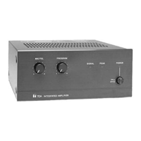
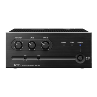
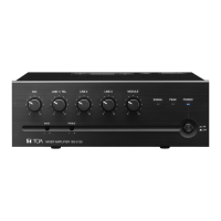
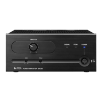
Identifies and describes front panel controls and indicators.

Protection function to be noted on operation

Explanation of the unit's internal protection circuit.

6. INPUT CONNECTIONS

[MIC input connections]

Diagram and explanation for MIC input connections.

[TEL and PROGRAM input connections]

Diagrams for TEL and PROGRAM input connections.

[AUX input connections]

Diagram and explanation for AUX input connections.

7. OUTPUT CONNECTIONS

[Output terminals]

Details on speaker outputs (4 Ω, 25 V, 70 V) and their connections.

[Connection of speaker cable]

Step-by-step instructions for connecting speaker cables.

[MOH output connections]

Diagram for MOH output connections (1 V / 600 Ω).

[OUTPUT 1 W output connections]

Diagram for 1 W output connections (8 Ω).

8. PLUG-IN MODULE INPUT PORT

8.1. Module Installation

Step-by-step guide for installing plug-in modules.

8.2. Module Selector Switch Settings

How to set the module selector switch for PAGE/BGM output.

9. EQUIPMENT SETTINGS

CAUTION

Warning regarding servicing instructions.

9.1. Mute Function

Explanation of the unit's two mute functions, A and B.

9. EQUIPMENT SETTINGS

9.1.1. Mute operation A

Details on how to activate Mute operation A using signals or terminals.

9.1.2. Mute operation B

Details on controlling Mute operation B via the mute terminal.

9. EQUIPMENT SETTINGS

9.2. TEL Input Impedance Selection

How to change TEL input impedance using jumper switch JP204.

9.3. AUX, PROGRAM, MODULE (BGM) Output Selection

Using jumper settings to select AUX, PROGRAM, BGM outputs.

9.4. Phantom Power On/Off Setting for Microphone Input

How to set phantom power using jumper switch JP201.

9. EQUIPMENT SETTINGS

9.5. Changing MIC and PROGRAM Input Types

Procedures to change MIC/PROGRAM inputs to transformer balanced types.

9.5.1. MIC input

Installing IT-450 transformer and cutting jumper wires for MIC input.

9.5.2. Program input

Installing IT-453A transformer and cutting jumper wires for PROGRAM input.

10. INSTALLATION

11. RACK MOUNTING BRACKET ATTACHMENT

12. CONTROL SETTINGS

13. DIMENSIONAL DIAGRAM

14. BLOCK DIAGRAM

15. SPECIFICATIONS

Related product manuals