FUEL SYSTEM
3-23
3-/ 4-Cylinder
2. Invert carburetor and install following components. Tighten jets
securely but do not use threadlocker:
• Main nozzle and main jet.
• Slow jet and plug.
• Float valve assembly.
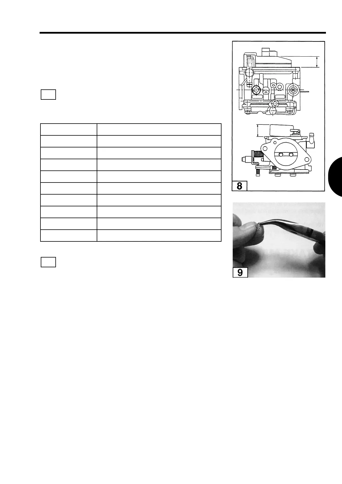
3. Check the float height with the carburetor inverted on a
flat surface. Measure the distance between the top of the
float and the float chamber surface at the opposite side of the
needle valve.
NOTE
If float height is not correct, remove the float valve
assembly and make minor adjustments by slightly
bending the tabs on the float hinge clip. Models 40
and 50 cannot be adjusted.
4. Install new gasket on float chamber.
5. Install float chamber, and tighten screws in a criss-cross pattern.
6. Install drain screw and new o-ring gasket.
7. Place carburetor in upright position and install gasket plates (if
equipped), new gasket(s), and carburetor cover.
8. Install pilot and throttle stop screws and springs. DO NOT
interchange springs.
MODEL FLOAT HEIGHT
40D / 40D2 0.591 in (15.0 mm)
500 / 50D2 0.591 in (15.0 mm)
60B / 60C 0.551 in (14 mm)
70B / 70C 0.551 in (14 mm)
80A 0.768 in (19.5 mm)
90A 0.768 in (19.5 mm)
115A2 0.768 in (19.5 mm)
120A2 0.768 in (19.5 mm)
140A2 0.768 in (19.5 mm)
8
9
T1036
T1037
 Loading...