Operation and Maintenance Manual
4/13
1. Installation
1.1. Installation of common baseplate
Installation and centering of the pump should be performed by skilled workers. Improper installation and
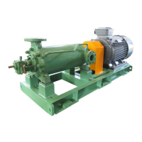
centering would cause various troubles during the pump running. When the pump and its driver are shipped as directly
coupled on the common baseplate, they have already been leveled and centered completely at our fabrication shop
before shipment.
However, install the common baseplate (with pump and driver properly in the sequence given below and recheck
the level and centering of pump and its driver).
(1) Prepare packers (steel wedges) and several kinds of 1 mm ~ 0.1 mm thick levelling shims.
(2) After complete cure-up of the pump foundation, place and position packers on the foundation at the both sides
of each anchor bolt seat so that the common bed can be put on the packers later on. Thereafter, grout
concrete on the foundation floor at each packer position and re-place and reposition the packers on the
concrete. In this case, don't fail to keep each packer right horizontal after adjusted by use of a level. The
height of each packer is to be fine-adjusted by insertion of shim(s) when the common bed is installed thereon.
Accordingly, at this stage only horizontality adjustment of the packers is sufficient.
(3) After complete cure-up of the concrete with packer on, temporarily install the common baseplate (with pump
and driver) on the packers and check the center height of the pump. Furthermore, hold a level on the
discharge flange to make fine-adjustment of the pump horizontality in both axial and crosswise directions by
inserting previously prepared levelling shims between the baseplate and each packer.
(4) After the pump was positioned and levelled, make pre-center alignment between the pump and the driver
using a centering jig (refer to 1.2 for the detail). In this case, recording the numeral date on pre-alignment will
be helpful when the direct coupled condition is checked.
(5) After pre-centering, grout concrete in each anchor bolt holder.
(6) After complete cure-up of the concrete in each anchor hole, tighten each anchor bolt nut with uniform
tightening torque. In this case, check and readjust the center alignment between coupling halves, based on
the recorded numeral pre-alignment data.
(7) After the above check, grout mortar under the common bed till it reaches entirely all the corners of the bed so
that no cavity exists under the bed.
(8) After completion of all the above items, connect the suction pipe and discharge pipe to the respective flanges
of the pump.
1.2. Direct Coupling
The pump shaft and the driver shaft must be centered in line. Therefore, make centering in the following
procedure without fail.
(1) For centering of the coupling, put a straightedge on the both coupling halves and insert a wedge gauge in
the axial clearance between the coupling halves, as illustrated in Fig. 2, to check run-out of the coupled
shafts.
Fig. 2 Aligning a non-spacer type flexible coupling
 Loading...