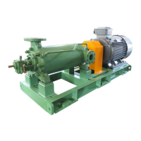
The CAL pump is a single-stage, axial single-suction centrifugal pump designed for vertical (upward) discharge. Its construction features a back pull-out type pump casing with integral-casted axial suction and top discharge nozzles, and a support foot. This design allows for disassembly and internal inspection without removing the casing (1020) from the piping. The pump is suitable for various applications, with different configurations available for shaft seals and lubrication types.
Function Description:
The primary function of the CAL pump is to transfer liquids. The impeller (2300), equipped with a balance hole, minimizes axial thrust. The design ensures that pumped liquid at the discharge side does not return to the suction side by maintaining a minimum sliding clearance between the casing wearing ring (5020) and the impeller. The pump can be driven by a motor, and proper installation and centering are crucial for its long-term satisfactory operation.
Important Technical Specifications:
- Casing: Back pull-out type volute casing (1020) fixed with the casing cover (1610) and bearing housing (3300) by bolts. A flat gasket (4000.3) seals the pumped liquid between the volute casing and casing cover. Some models (125-400, 200-250, 150-315, 150-400) feature a double volute casing structure to reduce radial thrust.
- Impeller: Installed on the shaft (2100) and fixed with Hard Lock Nut® (9233), which consists of two pieces (bottom nut - convex type, upper nut - concave type) with looseness preventive function.
- Shaft Seal: Available in two types: mechanical seal and gland packing.
- Mechanical Seal Type: Requires almost no maintenance during running. Wearable parts (seat 4750, washer 4720) may eventually wear, with replacement intervals depending on running conditions, liquid lubricity, and impurities. Spare parts for mechanical seals should always be stocked. Mechanical seals should not be operated dry and require priming before starting. Slight leakage at the beginning of operation is normal until the seal stabilizes.
- Gland Packing Type: The gland packing (4610) and the shaft surface must remain smooth. Scratches or uneven/over-tightening of the gland (4520) can cause overheating or quick wear. When replacing, use new packing material suitable for the pumping liquid, inserting it into the casing cover (1610) with mating faces shifted by 90 degrees. Ring-shaped molded packing is recommended. If string-shaped packing is used, a 45° cut is advised. The gland should be slightly recessed from the casing cover and lightly tightened, then re-tightened after a period of running to allow approximately 10 to 20 cc/min liquid leakage.
- Bearings: The pump shaft (2100) is supported by two ball bearings (3210) fitted on the shaft within the bearing housing (3300).
- Grease Lubricated Bearings: Require inspection and control of bearing temperature and timely replacement. Maximum permissible temperature is 90°C on the bearing housing surface or ambient temperature plus 55°C. Standard replacement interval is approximately 9000 hours for continuous operation, or every two years for short-time operation. Bearings should be replaced along with the shaft (2100) as a set (2101). Uses "Non-contact double rubber seal type deep groove ball bearing (Clearance C3)".
- Oil Lubricated Bearings: Require inspection and control of bearing temperature and lubricating oils, as well as timely ball bearing (3210) replacement. Maximum permissible temperature is 75°C on the bearing housing surface or ambient temperature plus 40°C. Lubricating oil level should be checked with the oil gauge (6430) or constant level oiler (6380). For new bearings, replace all lubricating oil after the initial 300 hours, then every 3,000 hours. Replacement intervals are similar to grease-lubricated bearings (9000 hours or two years). Uses "Open type deep groove ball bearing (Clearance C3)".
- Sliding Clearance: Design value between case wearing ring and impeller sliding surface is Ø0.4 mm for FC material (tolerance Ø1.0 mm) and Ø0.6 mm for SCS material (tolerance Ø1.2 mm). If exceeded, replace the case wearing ring.
Usage Features:
- Transportation: When transporting the pump coupled to a motor, use a wire rope applied to both pump and motor (not to the motor's eye-bolt).
- Installation: Requires skilled workers for installation and centering. Incorrect installation can lead to vibration and failure. The base plate should be leveled using packers and shims. After concrete curing, foundation bolts should be tightened.
- Direct Coupling: Pump and motor shafts must be aligned. Rotational direction of the motor should be checked before direct coupling (clockwise when facing the pump from the motor side). Checking rotational direction with the pump directly connected can damage the mechanical seal. Coaxiality (A) and parallelism (B1-B2) should not exceed 0.05 mm for flanged flexible shaft joints and 0.5 mm for rubber shaft joints.
- Piping: Avoid applying force from piping to the pump to prevent abnormal vibration. Minimize suction line losses by avoiding acute changes in pipe section or bending, and select pipe sizes for flow velocity of 3m/s max. Suction pipes should slope upward towards the pump to prevent air pockets. Use eccentric taper tubes if suction pipe diameter differs from the pump suction port. Install check valves between the pump discharge port and the discharge valve. Use strainers in the suction line to prevent foreign matter from entering the pump, with an effective area 3 to 4 times the suction sectional area. Small piping should also be checked for foreign matter. Add flexible pipes if high temperature or temperature fluctuations are expected to prevent thermal expansion load on the pump.
- Starting: Before initial operation, verify correct motor rotational direction, proper shaft connection and centering, small pipes connected, strainer clear, suction valve fully open, discharge valve fully closed, pump internally full with liquid, and no air purged. Check for leakage or abnormal conditions. Turn on/off the motor switch immediately to confirm smooth running and quiet stopping. Then, slowly open the discharge valve to reach the specified flow rate.
- Stopping: Fully close the discharge valve (unless a check valve prevents water hammer), switch off the motor, and ensure the pump slows down smoothly. If the pumped liquid may freeze, drain the liquid from inside the pump and the water-cooled jacket.
- Start/Stop Frequency: Frequent start/stop operations can cause pump/motor faults. For 2P type, up to once in 5 hours; for 4P type, up to twice in one hour.
- Meters and Gauge: Pressure or compound pressure gauges are recommended on the pump body/suction piping and discharge piping, with gradations covering 150% of maximum operating pressure. Use gauge cocks, and anti-corrosion gauge cocks for corrosive liquids. Keep gauge cocks closed except when reading pressure.
- Quench: For carbon bush type, quench flow rate is 1.0 liter/min or less, pressure 0.03 MPaG or less. For oil seal type, use liquid with high lubrication property.
- Jacket Water Cooling: Cooling water temperature 30°C or less (at inlet), pressure 0.3 MPaG or less. Do not use liquid with strong causticity.
- External Flushing: Flow rate 4 to 5 L/min. Pressure depends on use conditions.
Maintenance Features:
- General Maintenance: During operation, check for abnormal noise, vibration, suction pressure, discharge pressure, and motor overload. Stop the pump immediately if abnormalities are found.
- Disassembly and Reassembly: The CAL pump's back pull-out design allows disassembly without removing the volute casing from the base plate or pipelines.
- Disassembly Steps: Remove coupling guard, motor, drain pumped liquid, disconnect small pipes, remove bolts for volute casing/casing cover/support foot, remove bearing housing/casing cover/rotor, drain lubricating oil (if oil lubricated), unscrew Hard Lock Nut® and remove impeller/washer/key, disassemble shaft seal (mechanical seal or gland packing), separate casing cover from bearing housing, remove labyrinth (if grease lubricated) or drip (if oil lubricated), separate pump side coupling from shaft, remove bearing covers, pull shaft out of bearing housing (with ball bearings left in), and remove ball bearings (if replacement needed) by heating. Replace flat gaskets and O-rings when disassembling.
- Reassembly Steps: Follow reverse sequence of disassembly. Wash all components and prevent dust adhesion. Press-fit grease-lubricated bearings onto the shaft; heat oil-lubricated bearings to 110-120°C and shrink-fit them. Avoid damaging sealing surfaces. Fasten Hard Lock Nut® (bottom nut first, then upper nut). Recheck direct-coupled condition and restart pump. Slight leakage from mechanical seal is normal initially.
- Inspection and Maintenance of Disassembled Parts: Check casing cover for scale/rust, O-ring/cushion ring insertion parts for flaws, sliding surfaces for wear. Mechanical seals should be replaced or re-lapped after overhaul. Thoroughly wash disassembled parts.
- Long-Term Storage: If the pump is left unused for a long period, perform break-in operation for approximately 10 minutes once or twice a month, or turn the shaft (2100) manually.
- Ordering Spare Parts: Provide pump type & size, product number, production date, parts name, material, and quantity. Recommended spare parts and replacement cycles are provided in Table 4-1.
- Mechanical Seal Maintenance: Avoid dry running. Protect sliding surfaces from flaws. Replace or re-finish mechanical seal sliding surfaces after overhaul.
- Troubleshooting: A comprehensive troubleshooting guide is provided for common issues like "Pump cannot be filled with liquid," "Pump cannot start," "Insufficient discharge or incapable of pumping," and "Motor overload," with probable causes and corrective actions. If issues persist, contact an authorized distributor.