CAL Optional Design
- 4-
0.4.1. Volute casing
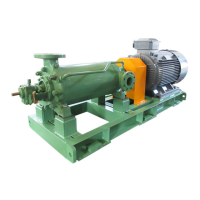
Back pull out type volute casing (1020) is fixed with the casing
cover (1610) and bearing housing (3300) at the driver side by
means of bolts. The flat gasket (4000.3) is inserted between the
mating surface of the volute casing (1020) and the casing cover
(1610) to seal the pumped liquid.
The following models provide double volute casing structure to
reduce radial thrust.
125-400, 200-250, 150-315, 150-400
0.4.2. Impeller
The impeller (2300) is installed with balance hole to balance the
greater part of axial thrust. Sliding clearance between the casing
wearing ring (5020) and the impeller is held to the minimum so that
pumped liquid at discharge side will not return to suction side.
The impeller is inserted through the shaft (2100), and fixed to shaft
(2100) with Hard Lock Nut® (9233). These Hard Lock Nut®
consist of two pieces of bottom nut (convex type) and upper nut
(concave type), special nuts having looseness preventive function.
0.4.3. Shaft seal
Casing cover (1610) as a part of the shaft seal is jointed, together
with bearing housing (3300), to volute casing (1020).
The shaft seal is available in two types; the mechanical seal type
and the gland packing type.
(1) In the case of mechanical seal type.
For the shaft seal construction, refer to Section 5 (P.13).
(2) In the case of gland packing type.
For the shaft seal construction, refer to Section 6 (P.21).
0.4.4. Bearing
The pump shaft (2100) is supported with two ball bearings (3210).
The ball bearings are fit on the shaft, which are placed in the
bearing housing (3300).
0.4.5. Shaft
The shaft components of each pump type are interchangeable with
those of other pump. As shown in Table 0-2, the shaft is available
in six sizes, which cover all models of the CAL pumps.
Table 0-2 Combination of pump size and shaft size
[The case of 4 pole motor drive]
Shaft size Pump size
25-360 32-125 40-125 65-125
32-160 40-160 50-160 65-150
32-200 40-200 50-200 65-190
35-470 80-150
80-190 80-200 100-190
32-250 40-250 50-250 65-240
80-240 100-245 80-250
65-310 80-310 100-310
45-470 50-315
45-470A 150-200
125-250
80-400
55-530 200-250
125-315
100-400 125-400
65-530 150-315
150-400
[The case of 2 pole motor drive]
Shaft size Pump size
25-360 32-125 40-125 65-125
32-160 40-160 50-160
32-200 40-200 50-200
35-470 80-160
45-470 80-200
32-250 40-250 50-250 80-250
1. Installation
1.1. Installation of base plate
Perform installation and centering of the pump by skilled workers.
Incorrect installation and centering will cause various troubles
while the pump is in running.
When the pump and the motor are directly coupled on a common
base plate, the pump has been correctly centered before shipment.
However, when installing the base plate at a local site, follow the
sequence below and, after installation, check that it is leveled as
specified.
(1) Prepare packers and several kinds of 1mm to 0.1mm thick
shims for leveling adjustment use, prior to installing.
(2) After complete setting of the foundation concrete, position
each packer at both sides from each foundation bolt and at
the portions equivalent to both side from each of the pump
and motor support feet. After positioning, place a mortar
onto the foundation floor (under the base plate) in each
packer position and the place each packer on the motor. In