NOTICE! If you don't do this adjustment, there's a risk that
the drawbar can loosen, or that operations can be louder than
normal.
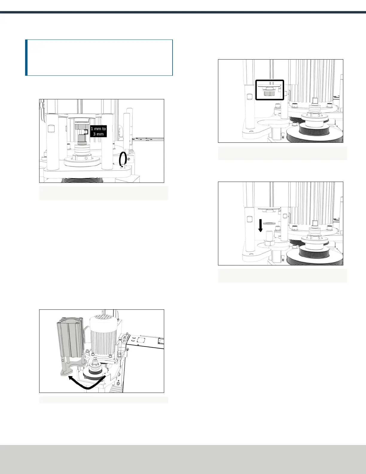
1. Examine the space between the hex head screw on the
Power Drawbar cylinder's rod and the top of the drawbar.
Figure 2-23: Example of a correctly spaced drawbar and
Power Drawbar cylinder.
2. Make sure that the gap is between 1 mm and 3 mm.
Depending on the size of the gap, do one of the following:
l If the gap is between 1 mm and 3 mm, you have
completed adjusting the initial setup.
l If the gap is less than 1 mm or greater than 3 mm, go to
Step 3.
3. Disconnect the shop's air supply from the Power Drawbar
button.
4. Pull out the quick-release pin.
5. Pivot the Power Drawbar cylinder assembly to the left so
that you can access the Power Drawbar cylinder's rod.
Figure 2-24: Power Drawbar cylinder pivoted to the left.
6. Use an adjustable wrench to remove the hex head screw on
the Power Drawbar cylinder’s rod.
Figure 2-25: Hex head screw on the Power Drawbar
cylinder's rod.
7. Remove the M16 washer from the Power Drawbar cylinder’s
rod, and set it aside.
Figure 2-26: M16 washer removed from the Power Drawbar
cylinder's rod.
8. Use an adjustable wrench to reinstall the hex head screw,
and then tighten it completely.
9. Pivot the Power Drawbar cylinder to the original location.
10. Push in the quick-release pin.
11. Reconnect the shop's air supply to the Power Drawbar
button.
12. Examine the space between the hex head screw on the
Power Drawbar cylinder’s rod and the top of the drawbar.
13. Makesure that the gap is between 1 mm and 3 mm.
Depending on the size of the gap, do one of the following:
l If the gap is between 1 mm and 3 mm, go to "Operating
the Power Drawbar" (page12).
l If the gap is less than 1 mm, go to Step 14.
14. Identify the three extra M16 flat washers provided.
©Tormach® 2018
Specifications subject to change without notice.
Page 10 tormach.com
TD10541: Owner's Guide: 770M® Power Drawbar (0618A)
TECHNICAL DOCUMENT