5. Move one spring washer on the drawbar, with the convex
side of the spring washer toward the drawbar head.
Figure 2-5: Example of moving the convex side of a spring
washer toward the drawbar head.
6. Move another spring washer on the drawbar, with the
concave side of the spring washer toward the concave side
of the spring washer from Step 5.
Figure 2-6: Example of moving the concave sides of two
spring washers together.
7. Put Anti-Seize on the edge of the contact surface between
the pair of spring washers that you put on the drawbar in
Step 5 and Step 6.
8. Repeat steps 5-7 for the remaining six spring washers. Make
sure that you put Anti-Seize on the spring washers at every
contact point.
9. Examine the stack of spring washers. Make sure that all
eight spring washers are installed on the drawbar and
arranged in four sets of opposing pairs.
Figure 2-7: Example of all eight spring washers installed on
the drawbar.
10. Identify the drawbar bushing that you set aside in Step 2,
and reinstall it on the drawbar. Make sure that the smaller
diameter of the drawbar bushing is toward the bottom of
the drawbar.
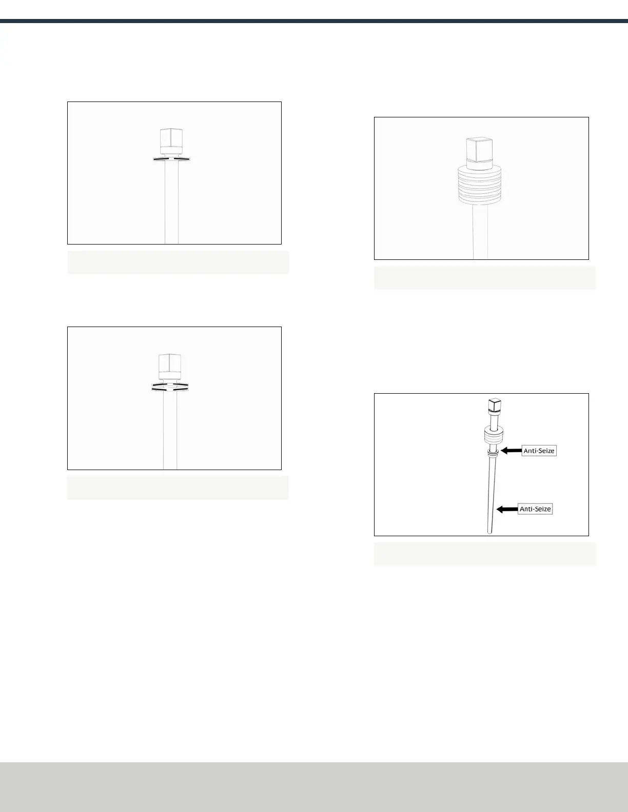
11. Put Anti-Seize on the top of the drawbar bushing.
12. Put Anti-Seize on the bottom threads of the drawbar.
Figure 2-8: Example of the locations to apply Anti-Seize on a
drawbar assembly.
13. Put Anti-Seize on the outside taper of the Tormach Tooling
System® (TTS®) collet. Make sure that there is no Anti-Seize
on the inside of the collet.
14. Insert the drawbar assembly into the spindle.
©Tormach® 2018
Specifications subject to change without notice.
Page 5 tormach.com
TD10541: Owner's Guide: 770M® Power Drawbar (0618A)
TECHNICAL DOCUMENT