23. Use a 5 mm hex wrench to install the 10 mm shoulder
screw on the Power Drawbar cylinder’s mount plate.
The unit is securely installed to the spindle head.
Figure 2-13: 10 mm shoulder screw installed on the Power
Drawbar cylinder's mount plate.
24. Identify the quick- release pin provided, and then insert it on
the Power Drawbar cylinder’s mount plate.
The quick-release pin allows the Power Drawbar cylinder to
pivot within the spindle motor cabinet.
Figure 2-14: Quick-release pin installed on the Power
Drawbar cylinder's mount plate.
NOTE: The Power Drawbar cylinder intentionally
floats.
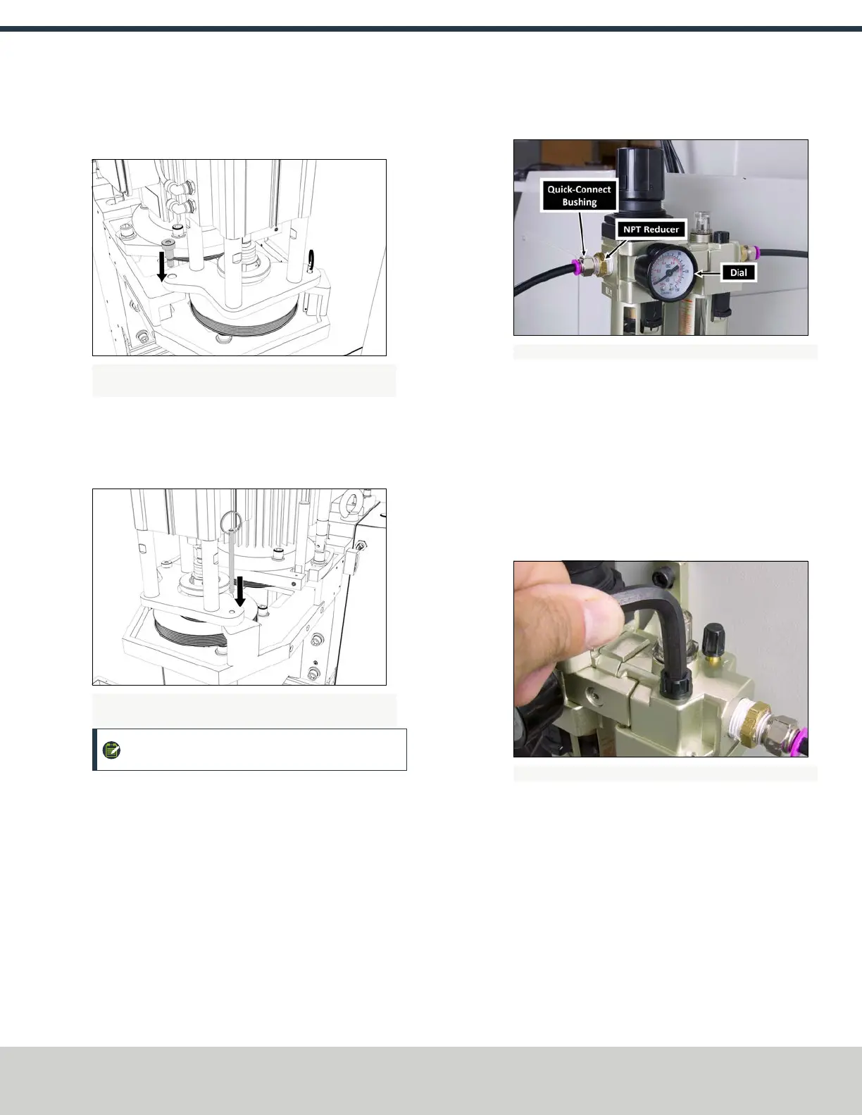
Install the FRLFilter-Regulator-Lubricator
1. Clean the FRL to make sure that it's free of dust.
2. Remove and discard the plastic inserts from the FRL.
3. Put two layers of thread seal tape on the threads of the dial.
4. Install the dial on the front of the FRL.
5. Install two quick-connect bushings into the two
NPTreducers.
6. Put two layers of thread seal tape on the threads of the NPT
reducers.
7. Install one NPT reducer into the valve housing on either side
of the FRL.
Figure 2-15: FRL installed on a mill's backsplash.
8. Determine the location to install the FRL.
9. Use the FRL bracket as a template to mark and drill two
holes.
10. Install the FRL bracket using your own hardware.
11. Connect the air lines to the quick-connect bushings that you
installed in Step 5.
Set Up the FRLFilter-Regulator-Lubricator
1. Use a hex wrench to open the fill port on the FRL.
Figure 2-16: Example of opening the fill port on an FRL.
2. Use a small funnel to fill the lubricator bowl with standard
air tool oil. Make sure that you only use oil that is
specifically designed for air tools.
3. Turn the adjustment knob halfway toward the +.
4. Flush all air bubbles from the system.
©Tormach® 2018
Specifications subject to change without notice.
Page 7 tormach.com
TD10541: Owner's Guide: 770M® Power Drawbar (0618A)
TECHNICAL DOCUMENT