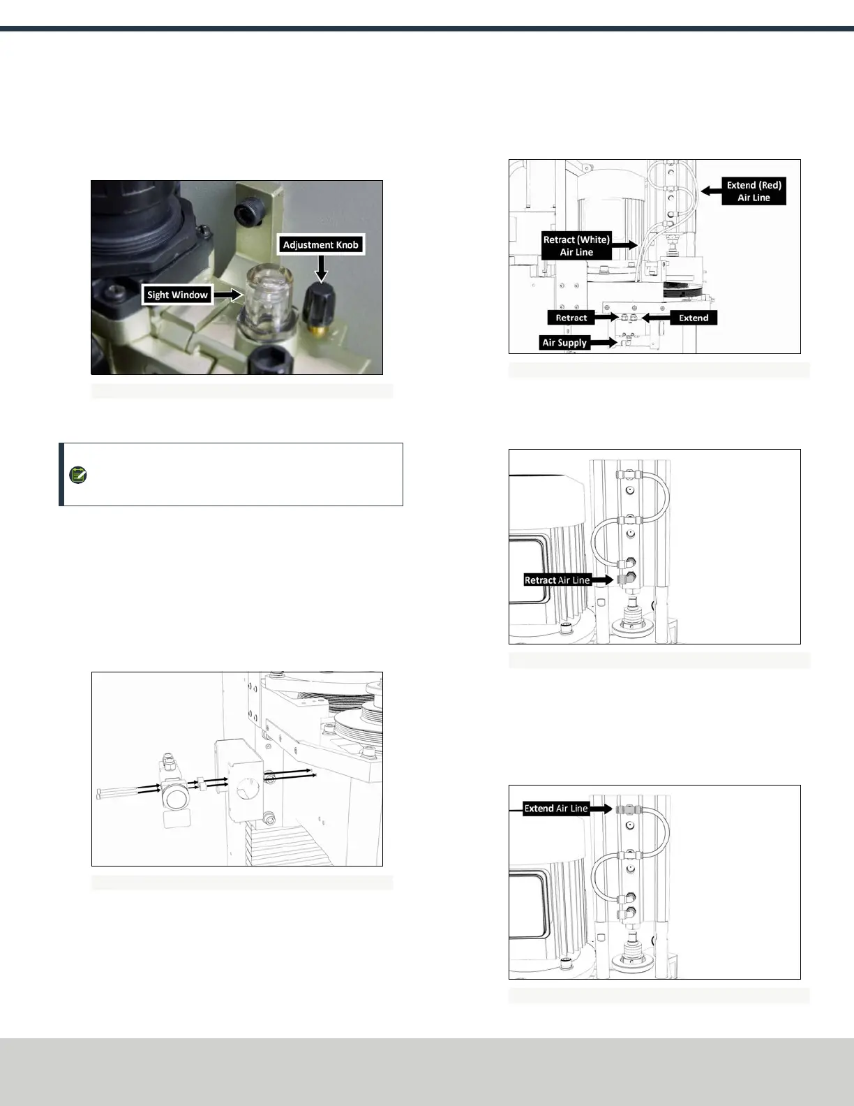
5. Examine the sight window for air bubbles. When there are
no air bubbles in the sight window, and a drop of lubricant is
on the bottom of the stem, turn the adjustment knob one-
quarter back.
Figure 2-17: Components to flush the air from the FRL.
Make Air Connections
NOTE: If you have an (optional) Automatic Tool Changer
(ATC), install it now.
1. Identify the button box assembly provided.
2. Use a 3 mm hex wrench to remove the four M5 × 0.8 - 10
button head screws securing the cover to the button box,
and then remove the cover.
3. Use two M4 × 0.7 - 50 socket head cap screws to install the
button box base, standoffs, and button assembly to the mill
head.
Figure 2-18: Button box base installed on the mill head.
4. Remove and discard the shipping plugs on the Power
Drawbar.
5. Identify the Retract (white) air line provided, and then
connect one end to the Retract port on the Power Drawbar
button.
Figure 2-19: Example of the Power Drawbar air line routing.
6. Route the loose end of the Retract air line to the Power
Drawbar cylinder, and then connect it to the bottom-most
elbow fitting.
Figure 2-20: Retract fitting on the Power Drawbar cylinder.
7. Identify the Extend (red) air line provided, and then connect
one end to the Extend port on the Power Drawbar button.
8. Route the loose end of the Extend air line to the Power
Drawbar cylinder, and then connect it to the upper-most tee
fitting.
Figure 2-21: Extend fitting on the Power Drawbar cylinder.
©Tormach® 2018
Specifications subject to change without notice.
Page 8 tormach.com
TD10541: Owner's Guide: 770M® Power Drawbar (0618A)
TECHNICAL DOCUMENT