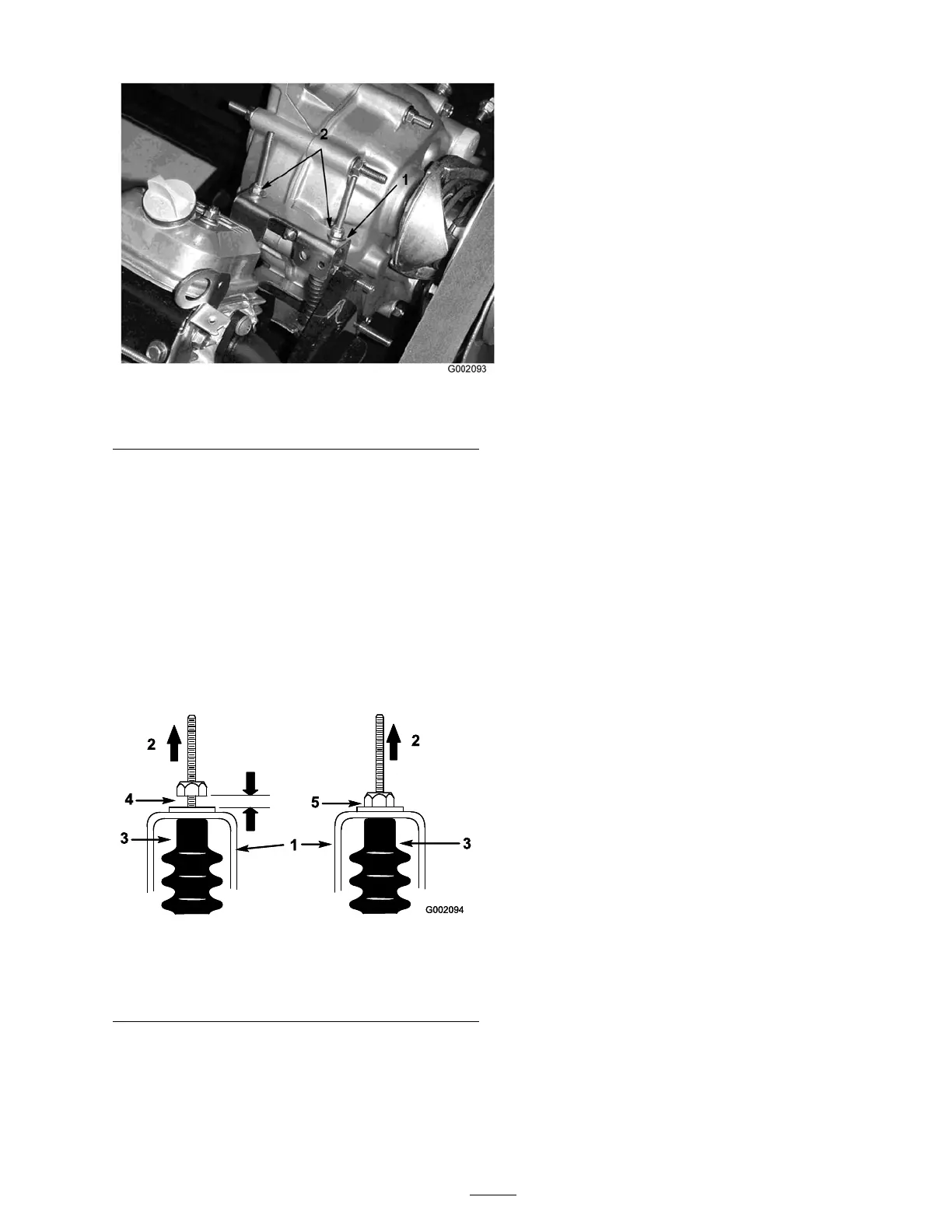
Figure 40
1. Neutral bracket 2. Locknuts
3. Tighten one of the loc kn uts ( Figure 40 ) just
enough to tak e the slac k out of the shift cable .
Note: Y ou m ust hold the threaded shaft
belo w the brac k et to tighten the loc kn ut on top .
4. Tighten the other loc kn ut just enough to tak e
the slac k out of the other shift cable .
5. Pull up on eac h shift cable an ensure that there
is no g ap betw een the n ut/w asher and the
neutral brac k et ( Figure 41 ). If there is a g ap ,
tighten the n ut.
Figure 41
1. Neutral bracket 4. Wrong, must tighten the
nut
2. Pull up 5. Correct adjustment
3. Cable boot
6. Star t the engine and shift into F orw ard,
R ev erse , and Neutral sev eral times to ensure
that the neutral brac k et is operating properly .
Inspecting the Tires
Chec k the tire condition at least ev er y 100 hours
of operation. Operating accidents , suc h as hitting
curbs , can damag e a tire or rim and also disr upt
wheel alignment, so inspect tire condition after an
accident.
Chec k the wheels to ensure that they are mounted
securely . T or que the lug n uts to 45-65 ft-lb
(61-88 N ⋅ m).
Adjusting the Front
Suspension
T he ride height of eac h side of the v ehicle can
be adjusted se parately . T he ride height should be
8-3/4 to 9-1/2 inc hes (22.2 to 24 cm) with the
follo wing parameters:
• T he tire pressure should be at 12 psi (83 kP a).
• T he v ehicle should be dri v en bac k and for th a
few times to relax the A-ar ms .
• Measure the ride height with the wheels facing
straight ahead and a 175-225 lb (79-102 kg)
operator in the dri v er’ s seat.
Note: T he dri v er should dri v e up to the
measurement area and sta y seated in the v ehicle
while the measurement is being tak en.
• Measure the ride height on a flat surface , from
the bottom of the front tongue to the g round.
1. J ac k the front end of the v ehicle off of
the g round; refer to J ac king the V ehicle in
Premaintenance Procedures , pag e 30 .
2. R emo v e the tra v el limiting bolt ( Figure 42 ).
3. Loosen the centering bolts in the front A-ar m
( Figure 42 ).
4. R emo v e the ride height adjustment bolt
( Figure 42 ).
37