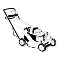
Figure29
1.Locknuts
6.Plasticcover(rearwheels
only)
2.Wheelspacer7.Lug
3.Bearing/hubassembly8.Bearing(2)
4.Bearingspacer9.Bolt
5.Wheelhalf
4.Separatethewheelhalvesfromthetirebyremoving
4boltsand4locknuts(Figure29).
Note:Ifyouremovethebearingsfromthe
bearing/hubassembly,removethembypressingon
thebearingspacer(Figure29).
AssemblingtheWheels
1.Positionthetireontoonewheelhalf,aligningthe
lugsoneach(Figure29).
2.Placethebearing/hubassemblyintothecenterhole
ofthewheelhalf.Ensurethatthelegsofthehubare
positionedovertheangeofthehole(Figure29).
3.Placetheotherwheelhalfontothebearing/hub
assembly,aligningthewheelandthetirelugsandthe
mountingholes(Figure29).
4.Using2fullythreadedscrewsorbolts(1/4-20x1.50
inch)andnon-lockingnuts,looselysecurethewheel
halvestogether.Mountthescrewsorboltsinthe
opposingholes(Figure29).
5.Checkthealignmentofallpartsandtightenthe
screws,alternatingfromsidetosideforauniformt,
untilthewheelhalvesaredrawntogether(Figure29).
6.Installthe2boltsand2locknutspreviouslyremoved
intheremainingholesinthewheelhalvesand
tighten.Removethe2longscrewsorboltsand
replacethemwith2boltsand2locknuts(Figure29).
7.Installthewheeltothepivotarmwiththebolts,
aspacer,andalocknut.Ensurethatthespaceris
positionedbetweenthewheelhubandthepivotarm
(Figure29).
ControlsSystem
Maintenance
AdjustingtheBladeBrake
Cable
Wheneveryouinstallanewbladebrakecableorreplace
thebladebrakeassembly,adjustthespringtensionon
thebladebrakecable.
1.Stoptheengineandwaitforallmovingpartstostop.
2.Disconnectthewirefromthesparkplug(Figure12).
3.Removethefueltankfromthetankbracket.
Note:Youdonotneedtodisconnectthefuelline
fromthefueltank.
4.Resetthecableadjusteronthehandlesothat1/4
inch(6mm)ofthethreadsshow,thentightenthe
nut(Figure30).
Figure30
1.Cableadjuster3.1/4inch(6mm)ofthreads
2.Nut
5.Loosenthecableclampscrewuntilthebrakecable
conduitslides(Figure31).
21