Replacing the Tracks (Model 22319)
W hen the trac ks are badly w or n, re place them.
1. Lo w er the loader ar ms , stop the engine , and
remo v e the k ey .
2. Lift/suppor t the side of the unit to be w ork ed
on so that the trac k is 3 to 4 inc hes (7.6 to 10
cm) off of the g round.
3. R emo v e the loc king bolt and n ut ( Figure 45 ).
4. Using a 1/2 inc h dri v e soc k et, release the
dri v e tension b y tur ning the tensioning screw
cloc kwise ( Figure 45 and Figure 46 ).
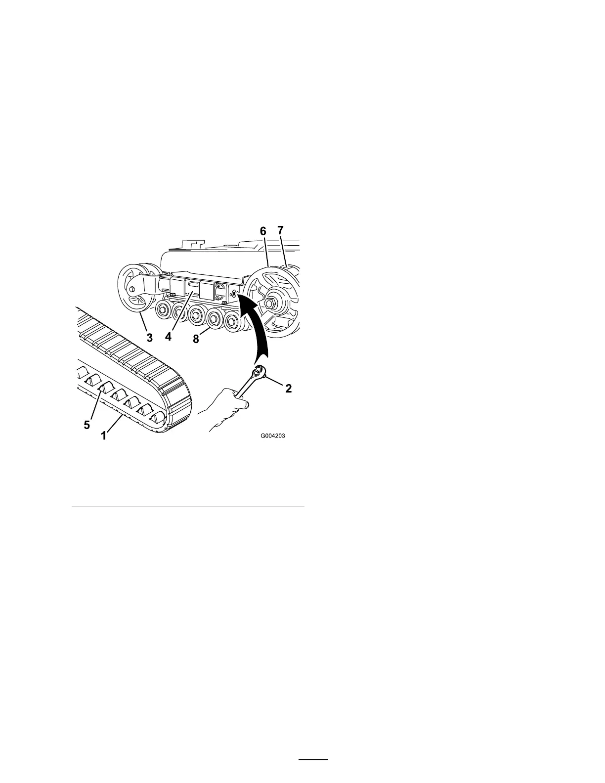
Figure 46
1. Track 5. Track lug
2. 1/2 inch socket 6. Drive sprocket
3. Tension wheel 7. Sprocket spacer
4. Fork tube 8. Road wheels
5. Push the tension wheel to w ard the rear of the
unit to mo v e the fork tube ag ainst the frame
( Figure 46 ). (If it does not touc h the frame ,
contin ue tur ning the tensioning screw until it
does .)
6. Begin remo ving the trac k at the top of the
tension wheel, peeling it off of the wheel while
rotating the trac k forw ards .
7. W hen the trac k is off of the tension wheel,
remo v e it from the dri v e sproc k et and road
wheels ( Figure 46 ).
8. Beginning at the dri v e sproc k et, coil the new
trac k around the sproc k et, ensuring that the
lugs on the trac k fit betw een the spacers on the
sproc k et ( Figure 46 ).
9. Push the trac k under and betw een the road
wheels ( Figure 46 ).
10. Star ting at the bottom of the tension wheel,
install the trac k around the wheel b y rotating
the trac k rearw ard while pushing the lugs into
the wheel.
11. T ur n the tensioning screw counter -cloc kwise
until the distance betw een the tension n ut and
the bac k of the fork tube ( Figure 44 ) is 2-3/4
inc hes (7 cm).
12. Align the closest notc h in the tension screw to
the loc king bolt hole and secure the screw with
the loc king bolt and n ut.
13. Lo w er the traction unit to the g round.
14. R e peat ste ps 2 through 13 to re place the other
trac k.
Replacing the Tracks (Model 22320)
W hen the trac ks are badly w or n, re place them.
1. Lo w er the loader ar ms , stop the engine , and
remo v e the k ey .
2. Lift/suppor t the side of the unit to be w ork ed
on so that the trac k is 3 to 4 inc hes (7.6 to 10
cm) off of the g round.
3. R emo v e the loc king bolt and n ut ( Figure 45 ).
4. Using a 1/2 inc h dri v e soc k et, release the
dri v e tension b y tur ning the tensioning screw
cloc kwise ( Figure 45 and Figure 47 ).
39