AdjustingtheAxleHeight
Adjusttheaxlepositiontotheselectedheight-of-cut
setting.RefertotheHeight-of-CutChart.
1.Disengagethebladecontrol(PTO)leverandset
theparkingbrakes.
2.Stoptheengineandwaitforallmovingpartsto
stopbeforeleavingtheoperatingposition.
3.Loosen,butdonotremove,the2axlepivotbolts
andthe2axleadjustmentbolts(Figure13).
Figure13
1.Axlepivotbolt2.Axleadjustmentbolt
4.Placeajackundertherearcenteroftheengine
frame.Raisethebackendoftheengineframeup
enoughtoremovethefront2axleadjustmentbolts
(Figure13).
Note:Usejackstandstosupportthemachine.
5.Raiseorlowertheengineframewiththejackso
thatyoucaninstallthefront2axleadjustmentbolts
inthedesiredholelocation(Figure13).
Note:Useataperedpunchtohelpaligntheholes.
6.Tightenall4boltsandlowerthemower.
7.Adjustthecontrolrodsandthebrakelinkages
asrequired.RefertoServicingtheBrakesand
AdjustingtheControlRods.
Important:Youmustadjustthecontrolrods
andthebrakelinkagewhenyouchangethe
axlepositionsforpropertractionandbrake
function.
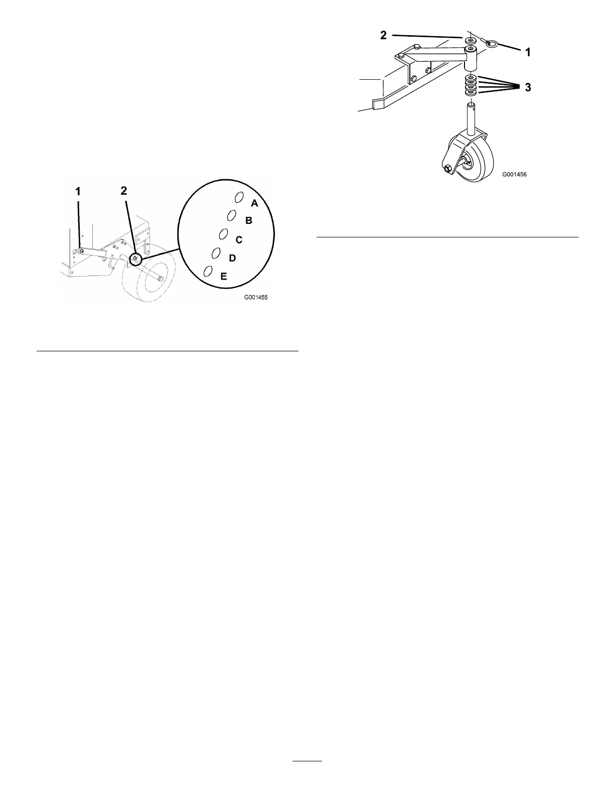
AdjustingtheCasterPosition
1.UsingtheHeight-of-CutChart,adjustthecaster
spacerstomatchwiththeaxleholeselected
(Figure14).
Figure14
1.Latchpin
3.Spacer,1/2inch(13mm)
2.Spacer,3/16inch(5mm)
2.Removethelatchpin,slidethecasterfromthe
support,andchangethespacers(Figure14).
3.Installthecasterinthesupportandinsertthelatch
pin(Figure14).
AdjustingtheFlowBafe
Themowerdischargeowcanbeadjustedfordifferent
typesofmowingconditions.Positionthecamlockand
bafetogivethebestqualityofcut.
1.DisengagethePTO,movethemotioncontrol
leverstotheneutrallockedpositionandsetthe
parkingbrake.
2.Stoptheengine,removethekey,andwaitforall
movingpartstostopbeforeleavingtheoperating
position.
3.Toadjustthecamlock,swingtheleveruptoloosen
thecamlock(Figure15).
4.Adjustthebafeandcamlockintheslottothe
desireddischargeow.
5.Swingtheleverbackovertotightenthebafeand
camlock(Figure15).
6.Ifthecamdoesnotlockthebafeintoplaceoritis
tootight,loosentheleverandthenrotatethecam
lock.Adjustthecamlockuntilthedesiredlocking
pressureisachieved.
20