Maintenance
Note: Deter mine the left and right sides of the mac hine from the nor mal operating position.
Recommended Maintenance Schedule(s)
Maintenance Service
Interval
Maintenance Procedure
After the rst operating
hour
• Check the control cable both initially and after the rst hour of operation; adjust it
if necessary.
• Check for loose fasteners and tighten them if necessary.
Yearly
• Check the control cable and adjust it if necessary.
• Check for loose fasteners and tighten them if necessary.
• Inspect the rotor blades and have an Authorized Service Dealer replace the rotor
blades and scraper if necessary.
• Check the skids and the scraper and adjust them if necessary.
• Have an Authorized Service Dealer inspect the drive belt and replace it if necessary.
Yearly or before storage
• Prepare the snowthrower for storage.
Adjusting the Control Cable
Checking the Cable
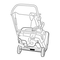
Important: Check the contr ol ca ble f or pr oper
adjustment initiall y , after the fir st operating hour , and
then ann uall y ther eafter .
1. Mo v e the control bar bac k to w ard the handle to remo v e
the slac k in the cable .
2. Ensure that a 1/16 to 1/8 inc h (2 to 3 mm) g ap exists
betw een the control bar and the handle ( Figure 20 ). T o
adjust the cable , refer to Adjusting the Cable belo w .
Figure 20
1. 1/16 to 1/8 inch (2 to 3 mm) gap
Important: T he contr ol ca ble must contain some
slack when y ou disenga ge the contr ol bar f or the
r otor blades to stop pr oper l y .
Adjusting the Cable
1. Unhook the end of the control cable spring from the
control bar ( Figure 21 ).
Figure 21
2. Mo v e the Z-fitting to a higher or lo w er hole in the
adjuster link as needed to obtain the 1/16 to 1/8 inc h
(2 to 3 mm) g ap betw een the control bar and the handle
( Figure 22 ).
Figure 22
1. Z-tting 2. Adjuster link
Note: Mo ving the Z-fitting higher decreases the g ap
betw een the control bar and the handle; mo ving it lo w er
increases the g ap .
10