8
DESCRIPTION USEQTY.
Skids 2
Flange-head bolts—3/4 in. (1.9 cm) 2
Flat washers 2
Installing the skids
Locknuts 3
Ignition key 1 Starting and stopping the engine
Installing the Auger/Impeller
Housing
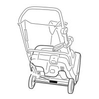
1. Remove the two flange-head bolts that secure the idler
pulley assembly to the engine frame, and remove the
idler pulley assembly (Fig. 2).
163
5
2
3
4
1
Figure 2
1. Idler pulley assembly
2. Flange-head bolts
3. Impeller pulley
4. Engine frame
5. Auger housing
Important Remove the idler pulley assembly to
prevent damaging it.
2. Align the holes in the auger/impeller housing with the
holes in the engine frame (Fig. 2).
3. Route the auger/impeller drive belt around the impeller
pulley (Fig. 2).
4. Secure the auger/impeller housing to the engine frame
with six 3/4-inch (1.9 centimeters) flange-head bolts.
5. Install the idler pulley assembly, aligning the idler
pulleys with the belts (Figs. 2 and 31).
6. Tip the snowthrower up on the front edge of the
auger/impeller housing, and block it in place.
7. Move the wheels to the rear position. Refer to
Operating the Power Shift Feature on page 15.
8. Push the latch arm to release the axle (Fig. 3).
m5009
1
2
Figure 3
1. Latch arm 2. Latch rod
9. Pull up on the axle while holding in the latch arm
(Fig. 3).
10. Continue pulling the axle forward until the latch rod
springs into the locked position (Fig. 3).
11. Install the lower belt cover on the underside of the
auger/impeller housing and the engine frame with two
1/2-inch (1 millimeter) flange-head bolts (Fig. 4).
164
3
2
1
Figure 4
1. Flange-head bolt (2)
2. Mounting tabs
3. Lower belt cover (shown
from bottom)
Note: Position the belt cover mounting tabs to the rear
of the engine frame member.
12. Lower the snowthrower onto its wheels.
13. Check the adjustment of the impeller cable; refer to
steps 4 through 8 of Adjusting the Auger/Impeller Drive
Belt on page 20.