SCAMP
BRAKE
SERVICING AND REPAIR
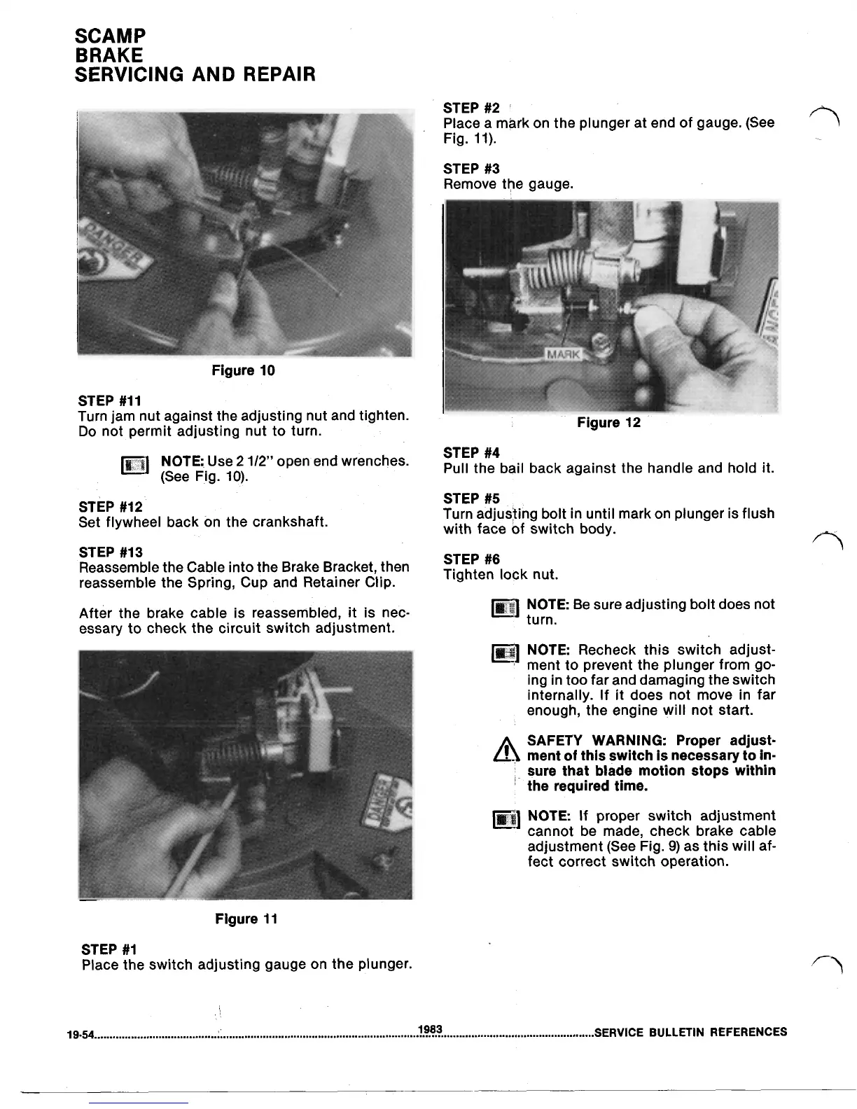
STEP
#2
Place a mark on the plunger at end of gauge. (See
Fig.
11).
STEP
#3
Remove the gauge.
Figure
10
STEP
#11
Turn jam nut against the adjusting nut and tighten.
Do
not permit adjusting nut to turn.
Figure
12
STEP
#4
(See Fig.
10).
Use
1/2”
Open
end
wrenches.
Pull the bail back against the handle and hold
it.
STEP
#12
Set flywheel back on the crankshaft.
STEP
#5
Turn adjusting bolt in until mark on plunger is flush
with face of switch body.
STEP
#13
Reassemble the Cable into the Brake Bracket, then
Tighten
nut.
reassemble the Spring, Cup and Retainer Clip.
STEP
#6
After the brake cable is reassembled,
it
is nec-
essary to check the circuit switch adjustment.
NOTE
Be sure adjusting bolt does not
turn.
NOTE
Recheck this switch adjust-
ment to prevent the plunger from go-
ing in too far and damaging the switch
internally.
If
it does not move in far
enough, the engine will not start.
SAFETY WARNING: Proper adjust-
ment
of
this switch is necessary
to
in-
sure that blade motion stops within
the required time.
NOTE
If
proper switch adjustment
cannot be made, check brake cable
adjustment (See Fig.
9)
as this will af-
fect correct switch operation.
Figure
11
STEP
#1
Place the switch adjusting gauge on the plunger.
19.54
SERVICE BULLETIN REFERENCES
1983