I
SCAMP
IGNITION CIRCUIT SWITCH
TESTING AND REPLACEMENT
Trouble shooting the circuit switch.
STEP
#7
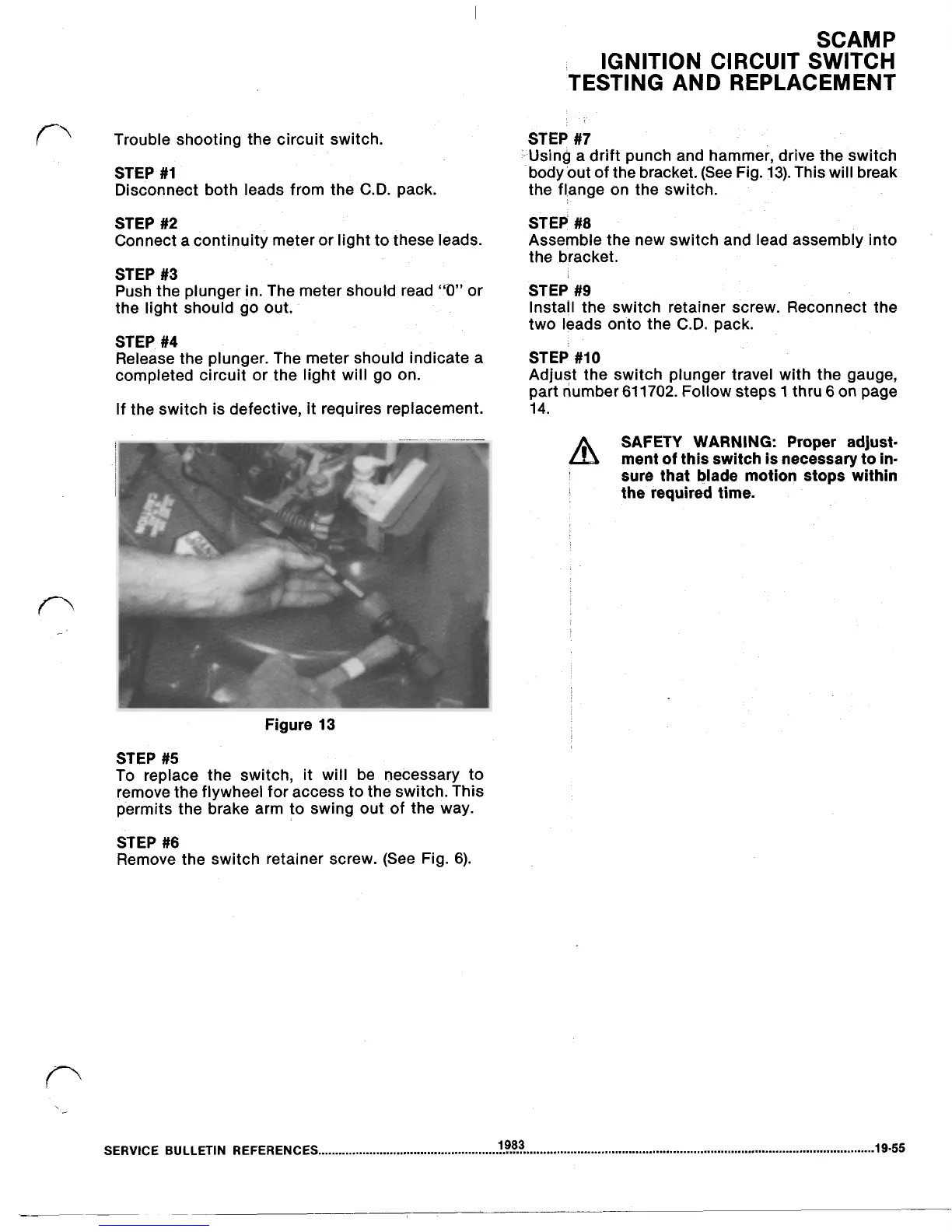
‘-Using a drift punch and hammer, drive the switch
STEP
#1
body out of the bracket. (See Fig.
13).
This will break
Disconnect both leads from the
C.D.
pack. the flange on the switch.
STEP
#2
Connect a continuity meter
or
light to these leads.
STEP
#3
Push the plunger in. The meter should read
“0”
or
the light should go out.
STEP
#4
Release the plunger. The meter should indicate a
completed circuit or the light will
go
on.
If
the switch is defective, it requires replacement.
STEP
#8
Assemble the new switch and lead assembly into
the bracket.
STEP
#9
Install the switch retainer screw. Reconnect the
two leads onto the
C.D.
pack.
STEP
#10
Adjust the switch plunger travel with the gauge,
part number 61 1702. Follow steps
1
thru
6
on page
14.
SAFETY WARNING: Proper adjust-
ment
of
this switch
is
necessary to in-
sure that blade motion stops within
the
required time.
Figure
13
STEP
#5
To replace the switch, it will be necessary to
remove the flywheel for access to the switch. This
permits the brake arm to swing out of the way.
STEP
#6
Remove the switch retainer screw. (See Fig. 6).
SERVICE
BULLETIN
REFERENCES
19-55
1983