Installation Procedure
To assure maximum performance from your 640 Series
Rotary Sprinklers, read these instructions completely prior to
installing or servicing the sprinkler.
Construct Swing Joints
1. Construct triple swing joints for each sprinkler as shown
in Figure 1. Use PVC or ABS pipe nipple for sprinkler
connection.
Note: On sites where the possibility of heavy equipment
rolling over a sprinkler exists, the swing joint will flex
preventing damage to the lateral or main lines. On a new
installation in raw ground where the sprinklers are to be
initially installed above the finished grade and lowered
when new turf is established, the swing joint allows
sprinkler repositioning without changing risers. This is a
common and practical procedure which eliminates the
problem of dirt being accidentally introduced into the
lateral lines when a riser is changed.
2. Flush lines thoroughly prior to installing sprinkler.
3. Apply Teflon
™
tape on riser threads. Install sprinkler to
riser and tighten.
CAUTION
Use only Teflon tape on riser threads. Use of pipe dope or other types of sealing compounds can
cause deterioration of plastic threads and components.
4. Install sprinkler on riser. Align part-circle heads by rotating sprinkler body on riser until radius adjustment slot on top of the nozzle
rubber cover is positioned to the left side of the intended coverage area.
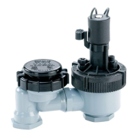
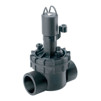
5. Valve-In-head models only: Remove tube retainer and cap from sprinkler fitting. Provide a service loop in control tube at
sprinkler to prevent binding. Slide tube retainer over end of control tube. Push control tube onto sprinkler fitting and secure with
tube retainer.
6. Install sprinklers flush with grade to 1/2 in. (0–13mm) below grade.
7. Backfill and compact soil around sprinkler avoiding contact with nozzle assembly.
Servicing the Sprinkler
Valve Replacement
WARNING
POSITIVELY SHUT OFF WATER SUPPLY AT SOURCE PRIOR TO DISASSEMBLING SPRINKLER.
BLEED ALL PRESSURE FROM SPRINKLER SYSTEM INCLUDING CONTROL TUBES. FAILURE TO
DEPRESSURIZE SYSTEM PRIOR TO VALVE SNAP RING REMOVAL MAY CAUSE VALVE MECHANISM
TO FORCIBLY EJECT FROM SPRINKLER BODY RESULTING IN POSSIBLE SERIOUS INJURY.
1. Remove cap set screw with 1/8 in. hex wrench and unscrew cap.
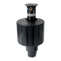
2. Remove nozzle container seal, nozzle retainer and nozzle/drive assembly from body.
3. Depress valve mechanism using a long screwdriver or similar tool (see CAUTION below).
CAUTION
Do not continue valve removal procedure if the valve cannot be pressed
down with minimum force. Confirm that water pressure is off and the
control tube is bled before continuing.
1
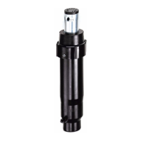
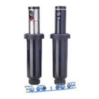
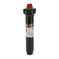
Installation and Service Instructions
640 Series Rotary Sprinkler
0 in.–1/2 in. (0–13mm)
FIGURE 1
Body
Snap
Ring
Valve