Maintenance
39
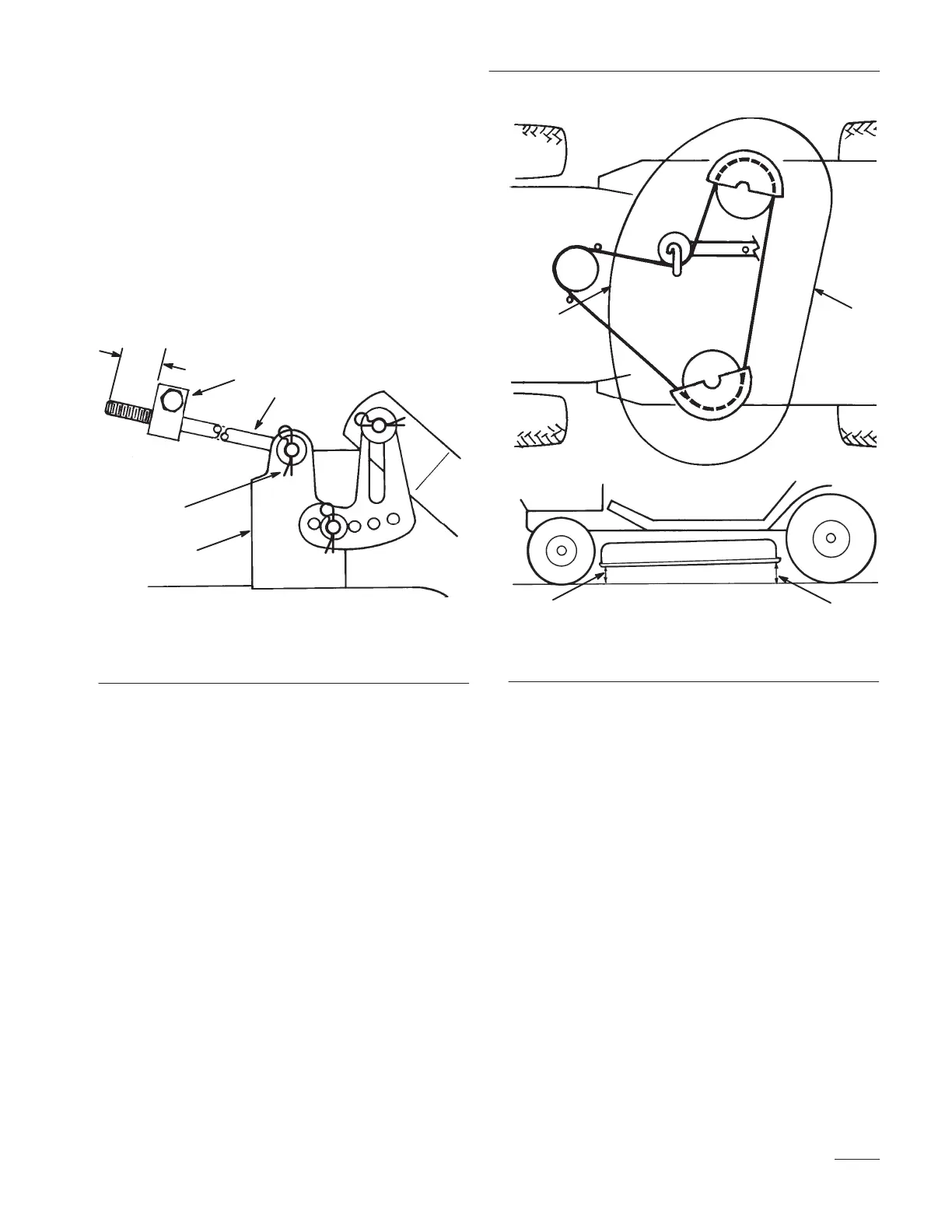
3. Measure the length of the rod extending out the
front of the adjusting block on the sides of the
chassis (Fig. 49). If the rod length is not 5/8”
(16 mm), remove the hair pin cotter and washer
from the end of the rod (Fig. 49), and turn the
rod until the 5/8” (16 mm) dimension is
obtained. Then install the end of the rod into the
hole in the mower mount and secure in place
with washer and hair pin cotter. Repeat
procedure on the opposite side.
5/8”
(16 mm)
1
2
3
4
1805
Figure 49
1. Hair pin cotter and washer
2. Leveling bracket
3. Front hole
4. Rear hole
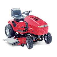
4. Check the front to rear slope by measuring
between the bottom of the mower
(front center and rear center) and the flat surface
(Fig. 50). If the front is not within a range of
1/8”–3/8” (3.5mm–10.5mm) lower than the rear,
an adjustment is required.
m–1892
12
1
2
Figure 50
1. Measure front center 2. Measure rear center
5. To adjust front-to-rear blade slope loosen front
pivot plate mounting bolts slightly (Fig. 51).
6. Rotate lock nuts on eyebolts to change
adjustment (Fig. 51).To raise the front of the
mower tighten the eyebolt lock nuts. To lower
the front of the mower loosen the eyebolt lock
nuts.
7. After adjusting both eyebolt lock nuts evenly,
check the front-to-rear slope again. Continue
adjusting eyebolts until the front blade tip is
0-3/8” (0-9.2 mm) lower than the rear blade tip
(Fig. 50).
8. When front-to-rear slope is correct, tighten the
pivot plate mounting bolts (Fig. 51).