15
Setup
Note: Determine the left and right sides of the machine from the normal operating position.
Loose Parts
Note: Use the chart below to verify all parts have been shipped.
DESCRIPTION QTY. USE
Rear wheels 2 Installing the wheels to the traction unit.
Suspension Seat
Nut
1
4
Install seat
Control lever—right
Control lever—left
Bolt, 3/8 x 1 in.
Spring washer, 3/8 in.
1
1
4
4
Installing the motion control levers.
Key
Operator’s Manual
Engine Operator’s Manual
Parts Catalog
2
1
1
1
Read before operating the machine.
Registration card 1 Fill out and return to Toro.
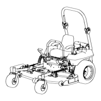
Installing the Drive Wheels
1. Uncrate the mower.
2. Remove the wheel nuts from the rear wheel hubs.
3. Align the holes. Mount the drive wheels with the valve
stem to the outside of the traction unit.
4. Secure the wheels using the wheel nuts provided.
Torque to 95 ft.-lb. (128 N⋅m).
Checking the Tire Pressure
Check the air pressure in the front and rear tires (Fig. 2).
Pressure: 13 psi (90 kPa)
m–1872
1
Figure 2
1. Valve stem