41
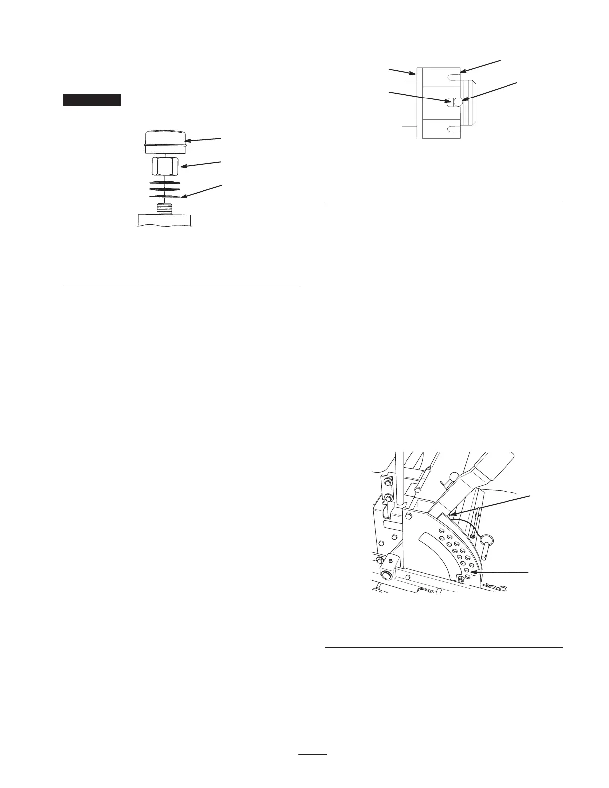
3. Tighten until the spring washers are flat and then back
off 1/4 turn to properly set the preload on the bearings
(Fig. 53).
Important Make sure that the spring washers are
installed correctly as shown in Figure 53.
1
M–4640
2
3
Figure 53
1. Spring washers
2. Locknut
3. Dust cap
Checking the Wheel Hub
Slotted Nut
Check after every 500 operating hours.
The slotted nut needs to be torqued to 125 ft.-lb. (170 N⋅m).
1. Stop the engine, set the parking brake, remove the key,
and disconnect the spark plug wire(s) from the spark
plug(s).
2. Remove the cotter pin.
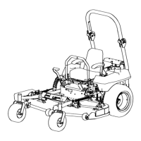
3. Torque the slotted nut to 125 ft.-lb. (170 N⋅m) (Fig. 54).
4. Check the distance from the bottom of the slot in the
nut to the inside edge of the hole. Two threads or less
should be showing (Fig. 54).
5. If more than two threads are showing, remove the nut
and install a washer between the hub and nut (Fig. 54).
6. Torque the slotted nut to 125 ft.-lb. (170 N⋅m) (Fig. 54).
7. Tighten the nut until the next set of slots line up with
the hole in the shaft (Fig. 54).
8. Install the cotter pin.
3
m–4638
1
2
4
Figure 54
1. Slotted nut
2. Two threads or less
showing
3. Hole in threaded rod
4. Washer (if needed)
Adjusting the Mower Level
1. Position the mower on a flat surface. Stop the engine,
set the parking brake, remove the key, and disconnect
the spark plug wire(s) from the spark plug(s).
2. Check the tire pressure of all 4 tires. If needed, adjust to
13 psi (90 kPa).
3. Set the anti-scalp rollers to the top holes or remove
them completely for this adjustment.
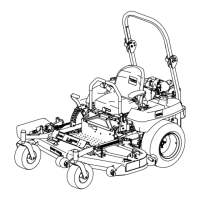
4. Raise the deck to the transport position and take all of
the force off of the two large deck lift springs by
loosening the nut in front of each spring (Fig. 55).
5. Place 2 thick blocks (1-1/2 in. [38 mm]) under the rear
left and right lower edge of the mower. Place 1 block
(2-1/4 in. [57 mm]) under the front center lower edge of
the mower. Lower the mower to the 2 in. (51 mm)
height-of-cut position (Fig. 55).
m–4164
1
2
Figure 55
1. Transport position
2. 2 in. (51 mm) height-of-cut