46
Leveling the Mower Side–to–Side
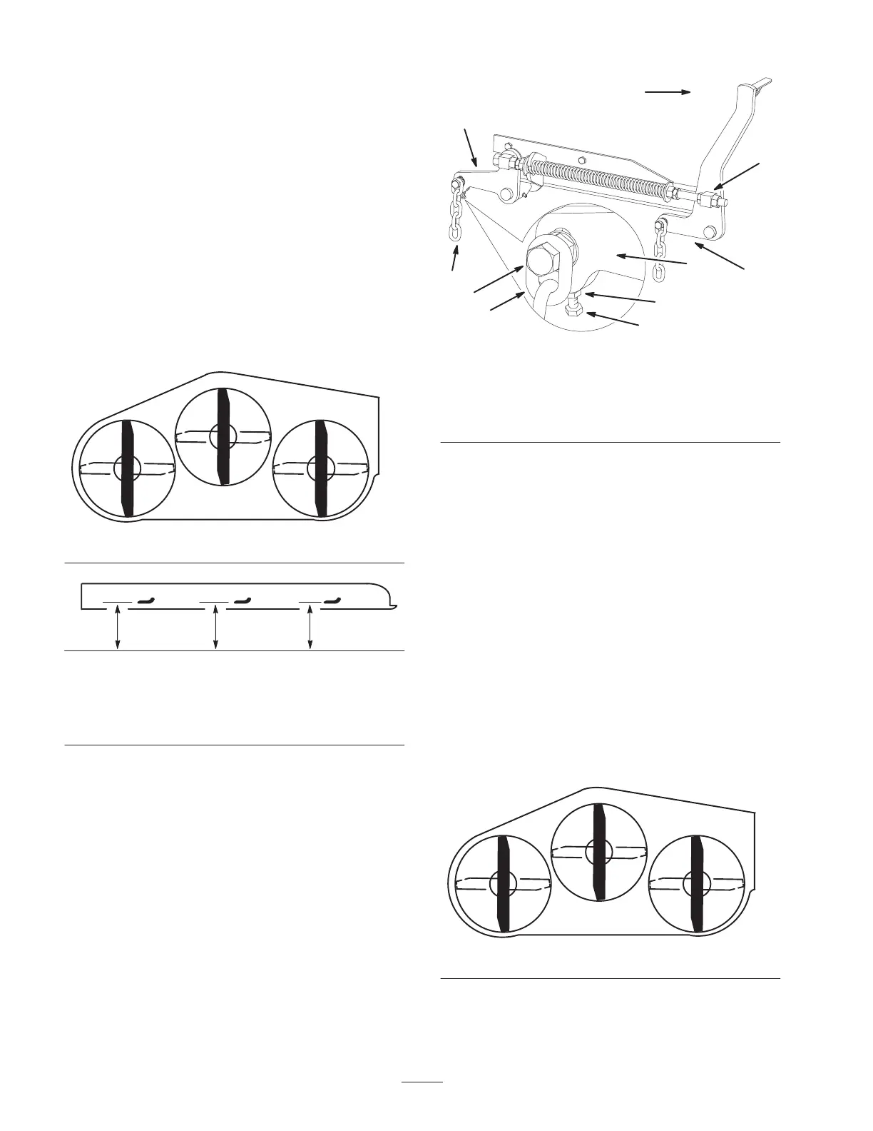
1. Position the right blade front-to-rear (Fig. 63).
2. Measure the right blade at the B location (Fig. 63),
from a level surface to the cutting edge of the blade tip
(Fig. 64).
3. Record this measurement. This measurement needs to
be 3–1/8 to 3–1/4 inches.
4. Position the left blade front-to-rear (Fig. 63).
5. Measure the left blade at the C location (Fig. 63), from
a level surface to the cutting edge of the blade tip
(Fig. 64).
6. Record this measurement. This measurement needs to
be 3–1/8 to 3–1/4 inches.
Front
B
m–1078
C
Figure 63
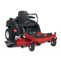
MEASURE FROM
CUTTING EDGE TO
A LEVEL SURFACE
m–2539
Figure 64
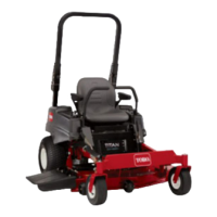
7. If the measurements at positions B or C are not
correct, loosen the bolt attaching the rear chain to the
rear support arm (Fig. 65).
8. Loosen the jam nut under the rear support arm and
adjust the adjustment bolt to get a measurement of
3–1/8 to 3–1/4 inches.
Note: It is recommended that both sides of the mower are
adjusted the same distance.
9. Tighten the jam nut under the rear support arm and
tighten the bolt securing the chain to the rear support
arm.
10. Adjust the opposite side if needed.
m–6830
1
1
5
4
3
Front
2
2
6
7
Figure 65
1. Rear chain
2. Rear support arm
3. Bolt
4. Jam Nut
5. Adjustment bolt
6. Front swivel
7. Front support arm
Adjusting the Front–to–Rear Mower Pitch
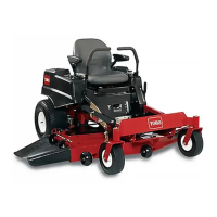
1. Position the right blade front-to-rear (Fig. 66).
2. Measure the right blade at the A location (Fig. 66),
from a level surface to the cutting edge of the blade tip
(Fig. 67).
3. Record this measurement.
4. Measure the right blade at the B location (Fig. 66),
from a level surface to the cutting edge of the blade tip
(Fig. 67).
5. Record this measurement.
6. The mower blade should be a 1/4 to 3/8 inch
(6 to 10 mm) lower at position A than at position B
(Fig. 66). If it is not correct, proceed to the following
steps.
Front
B
m–1078
A
Figure 66