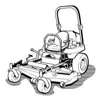
Figure 65
1. Rear chain 5. Adjustment bolt
2. Rear support arm
6. Front swivel
3. Bolt
7. Front support arm
4. Jam Nut
8. Loosen the jam n ut under the rear suppor t
ar m and adjust the adjustment bolt to g et
a measurement of 3-1/8 to 3-1/4 inc hes
( Figure 65 ).
Note: It is recommended that both sides of
the mo w er are adjusted the same distance .
9. Tighten the jam n ut under the rear suppor t
ar m and tighten the bolt securing the c hain to
the rear suppor t ar m.
10. Adjust the opposite side if needed.
Adjusting the Front-to-Rear Mower
Pitch
1. P osition the right blade front-to-rear
( Figure 66 ).
Figure 66
1. Measure here from blade
to hard surface
2. Measure at A and B
2. Measure the right blade at the A location, from
a lev el surface to the cutting edg e of the blade
tip ( Figure 66 ).
3. R ecord this measurement.
4. Measure the right blade at the B location, from
a lev el surface to the cutting edg e of the blade
tip ( Figure 66 ).
5. R ecord this measurement.
6. T he mo w er blade should be a 1/4 to 3/8 inc h
(6 to 10 mm) lo w er at position A than at
position B ( Figure 66 ). If it is not cor rect,
proceed to the follo wing ste ps .
Note: Both of the front swi v els need to be
adjusted the same amount to maintain equal
c hain tension.
7. Loosen the front swi v el jam n uts , at the front
of the right and left swi v els , appro ximately a
1/2 inc h (13 mm) ( Figure 65 ).
8. Adjust the lift n uts on both the left and the
right side of the mac hine to ac hiev e 1/4 to
3/8 inc h (6 to 10 mm) lo w er in front at A than
in the rear at B ( Figure 65 ).
9. Tighten both swi v el jam n uts ag ainst the front
swi v el to loc k the height.
10. Chec k to mak e sure there is equal tension on
the c hains and adjust ag ain if needed.
51