ProductOverview
g019888
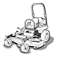
Figure4
1.Height-of-cutdecklift
pedal
6.Rollbar
2.Transportlock
7.Seatbelt
3.Parking-brakelever8.Fuelcap
4.Controls
9.Mowerdeck
5.Motion-controllever
10.Casterwheel
Controls
Becomefamiliarwithallofthecontrolsbeforeyou
starttheengineandoperatethemachine(Figure4
andFigure5).
g010363
Figure5
1.Hourmeter
6.Glow-pluglight
2.Ignitionswitch7.Engine-temperaturelight
3.Fuel-selectorvalve8.Throttlecontrol
4.Audiblealarm
9.PTOswitch
5.Glow-plugswitch
HourMeter
Thehourmeterrecordsthenumberofhoursthe
enginehasoperated.Itoperateswhentheengine
isrunning.Usethesetimesforschedulingregular
maintenance(Figure5).
Safety-InterlockIndicators
Therearesymbolsonthehourmeterthatindicate
withablacktrianglethattheinterlockcomponentis
positionedcorrectly(Figure6).
Battery-IndicatorLight
WhenyouturntheignitionkeyinitiallytotheRUN
positionforafewseconds,thebatteryvoltageis
displayedintheareawherethehoursarenormally
displayed.
Thebatterylightturnsonwhenyouturnontheignition
andthechargeisbelowthecorrectoperatinglevel
(Figure6).
g009610
Figure6
1.Safety-interlocksymbols
3.Batterylight
2.Hourmeter
ThrottleControl
Thethrottlecontrolstheenginespeed,andithasa
continuous-variablesettingfromtheSLOWtoFAST
position(Figure5).
Blade-ControlSwitch(Power
Takeoff)
Theblade-controlswitch(PTO)engagesand
disengagespowertothemowerblades(Figure5).
Neutral-LockPosition
TheNEUTRAL-LOCKpositionisusedwiththe
safety-interlocksystemandtodetermineNEUTRAL
position.
15