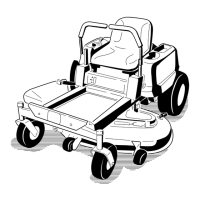
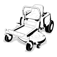
Removing the Mower Deck
W ARNING
Operating this machine without an approved
T oro front mount attachment increases
the possibility of operator entanglement
in the drive wheels or forward tip-over .
Entanglement or tip-over could cause serious
injury or death.
When operating this machine without an
approved T oro front mount attachment,
observe the following:
• Keep feet and clothing away from tires.
• Limit operation to minimum required to
install a different front mount attachment.
• Minimize speed and use extreme caution.
• Only operate on a at level surface.
• Do not operate up or down a trailer ramp.
• A void sudden acceleration or deceleration.
Important: Do not transport this machine without
an approved T oro front mount attachment.
1. Park the machine on a level surface, move the
speed-control lever to the N EUTRAL position,
disengage the blade-control switch (PT O), and
engage the parking brake.
2. Shut of f the engine, remove the key , and wait
for all moving parts to stop before leaving the
operating position.
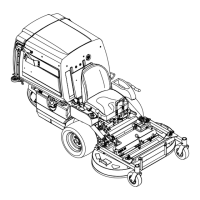
3. Raise mower deck up and latch with deck-locking
pins. Refer to Raising the Mower Deck into the
Service Position ( page 18 ) .
4. Remove the hairpin cotters and washers at the
top of the deck-lift-assist spring on each side of
the machine ( Figure 70 ).
g006788
Figure 70
1. Spring anchor pin under console
2. Secure springs with a washer and hairpin cotter
3. Slide the spring onto the spring-anchor pin
5. Remove the spring from the spring anchor .
Repeat for other side of the machine.
6. Unlatch the mower deck from the raised position
and slowly lower the mower deck to ground;
refer to Lowering the Mower Deck to the
Operating Position ( page 18 ) .
Note: The mower deck becomes heavier when
you remove the springs from the anchors. Lower
the mower deck carefully .
7. Remove the lynch pins at the front of the push
arms on both sides of the machine ( Figure 71 ).
59
 Loading...