g233982
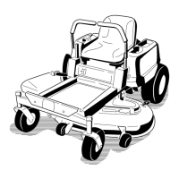
Figure 71
1. Push arm
2. L ynch pin
3. Push-arm tube
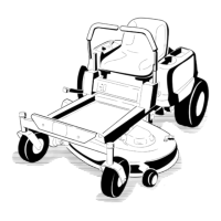
8. Loosen the bolts attached to the rubber guard
( Figure 72 ).
g036545
Figure 72
1. Bolts
2. Rubber guard
9. Unlatch the seat and disconnect the drive shaft
using the quick coupler at the jackshaft ( Figure
73 ). Refer to Unlatching the Seat ( page 21 )
g006785
Figure 73
1. Jackshaft 2. Drive shaft
10. Pull the mower deck forward to remove it from
the machine.
Installing the Mower Deck
Important: Do not transport the machine without
an approved T oro front mount attachment.
1. Park the machine on a level surface, move the
speed-control lever to the N EUTRAL position,
disengage the blade-control switch (PT O), and
engage the parking brake.
2. Shut of f the engine, remove the key , and wait
for all moving parts to stop before leaving the
operating position.
3. Roll the mower deck up to the machine with the
discharge tube down, making sure that the deck
springs are located above the drive wheel and
below the console on each side.
4. Unlatch the seat and tilt the seat forward.
5. Install the drive shaft onto the jackshaft ( Figure
73 ).
6. Align the mower-deck push-arm tubes to the
machine push-arms and push the mower deck
rearward.
7. Secure the push arms with the lynch pins on the
left and right sides of the machine ( Figure 71 ).
8. Align the upper portion of the rubber guard and
secure it with the attached bolts ( Figure 72 ).
9. Release the mower-deck-locking pins on each
side, raise the mower deck to the service
position and secure the deck latch onto the
hook. Refer to Raising the Mower Deck into the
Service Position ( page 18 ) .
60
 Loading...