16
1
m–7872
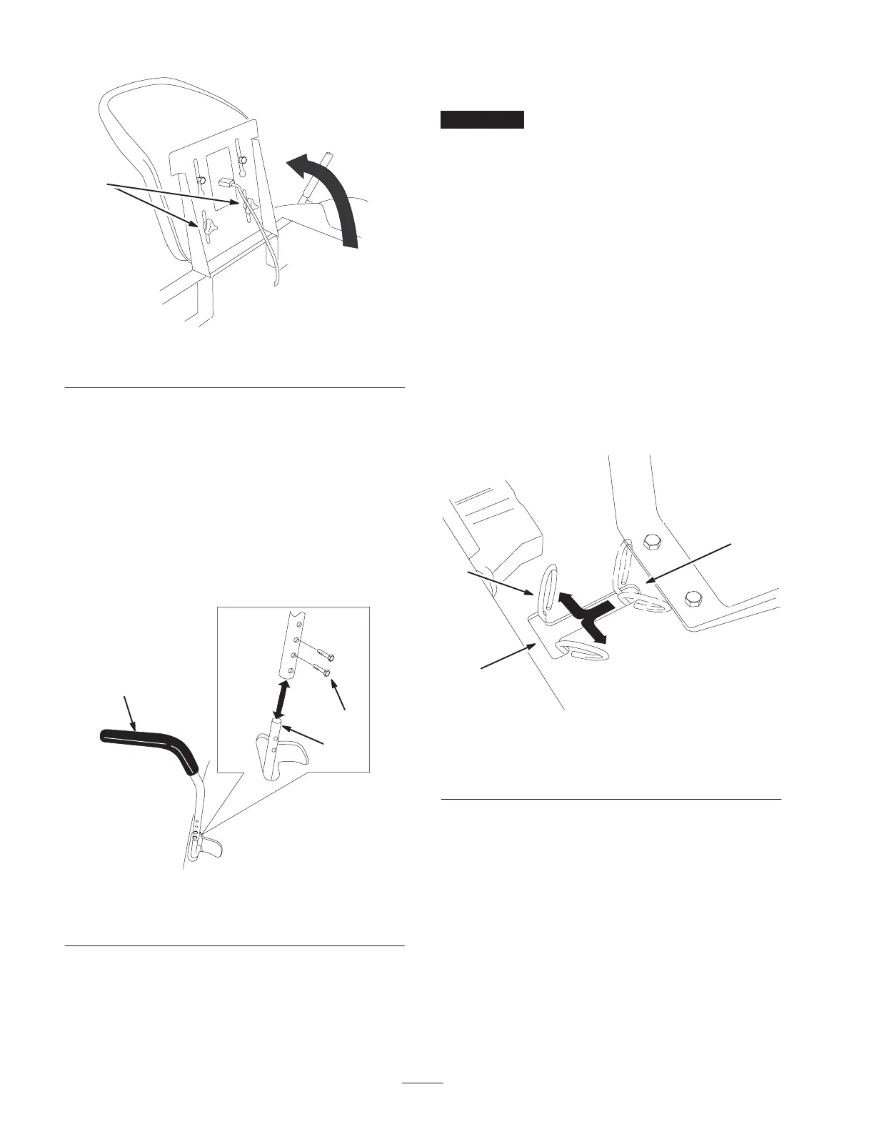
Figure 11
1. Adjustment knobs
Adjusting the Motion Control
Levers
The motion control levers can be adjusted higher or lower
for maximum operator comfort.
1. Remove the 2 bolts holding the control lever to the
control arm shaft (Fig. 12).
2. Move the control lever to the next set of holes. Secure
the lever with the 2 bolts (Fig. 12).
1
2
3
m–6417
Figure 12
1. Control lever
2. Bolt
3. Control arm shaft
3. Repeat the adjustment for the opposite control lever.
Pushing the Machine by Hand
Important Always push the machine by hand. Never
tow the machine because damage may occur.
To Push the Machine
1. Park the machine on a level surface and disengage the
blade control (PTO).
2. Move the motion control levers outward to engage the
parking brake, stop the engine, remove the key, and
wait for all moving parts to stop before leaving the
operating position.
3. Raise the seat to access the bypass levers (Fig. 13).
4. Move the two bypass levers forward and then outward
to lock them in place as shown in Figure 13.
5. Move the motion control levers inward to disengage the
parking brake.
The machine is now able to be pushed by hand.
3
1
m–7873
2
Figure 13
1. Bypass levers
2. Lever position for pushing
the machine
3. Lever position for
operating the machine
To Operate the Machine
Move the bypass levers to the inside and pull them
rearward, to the end the slot (Fig. 13).
Note: The machine will not drive unless the bypass levers
are disengaged.
 Loading...